|
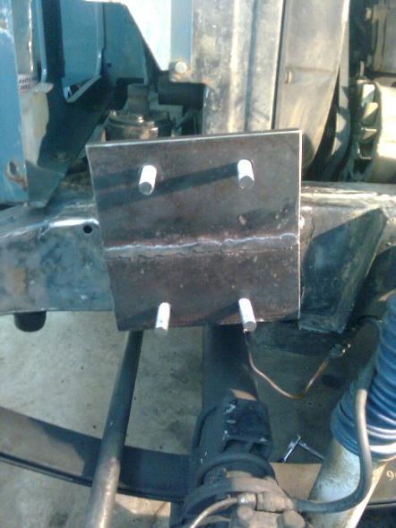
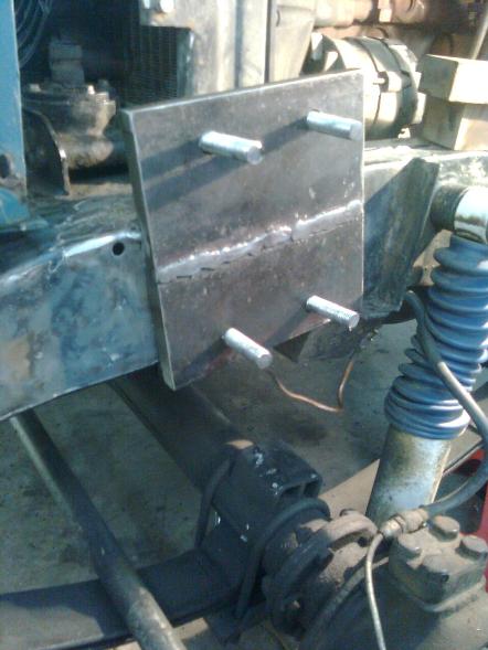
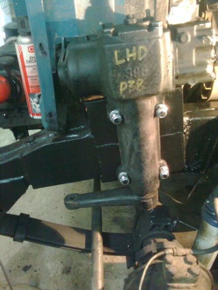
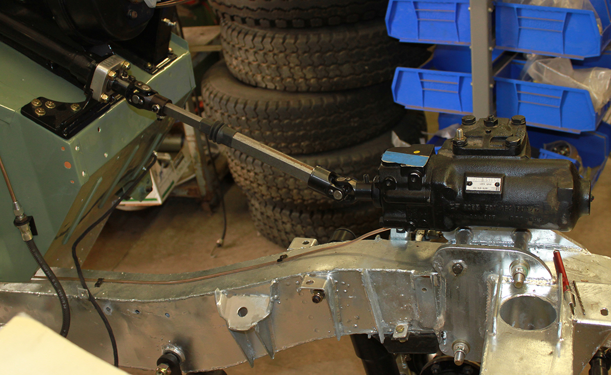
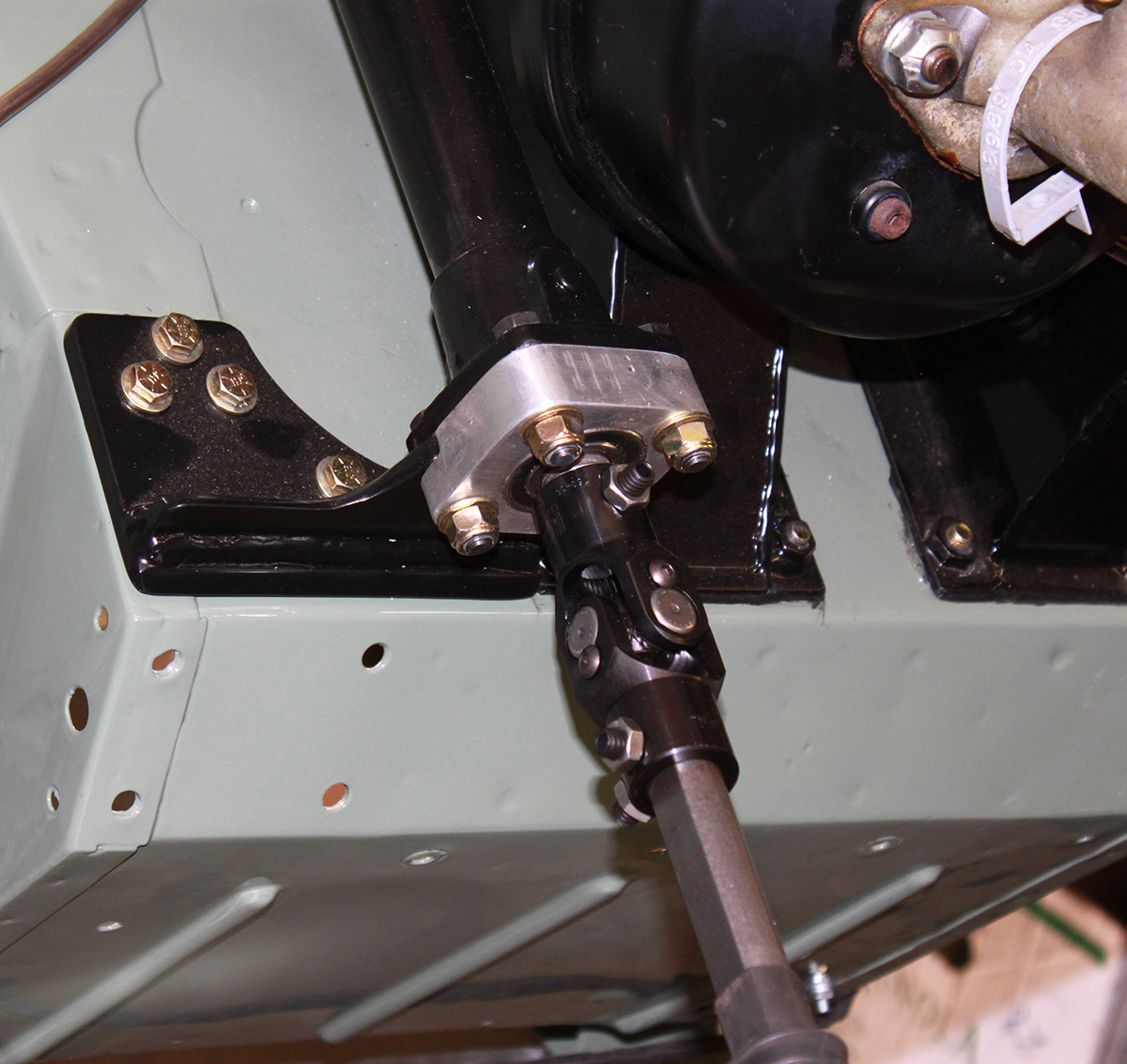
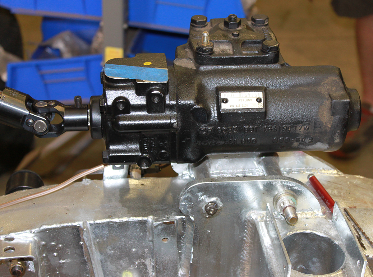
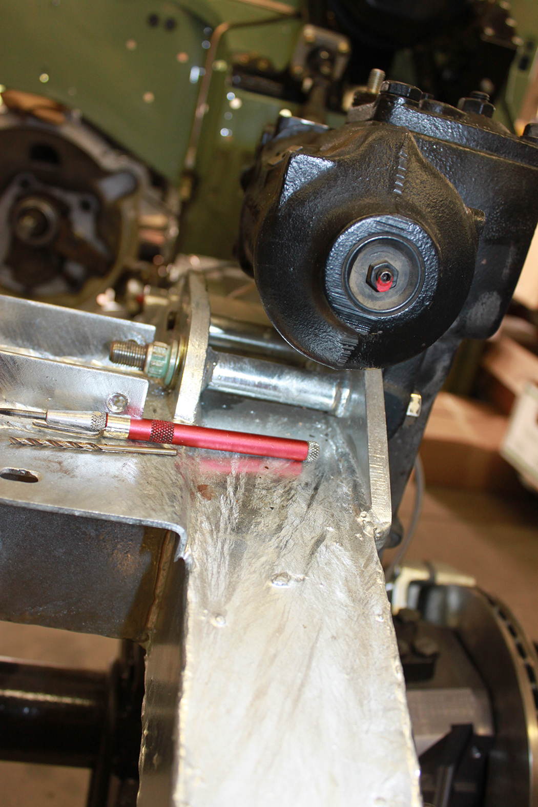
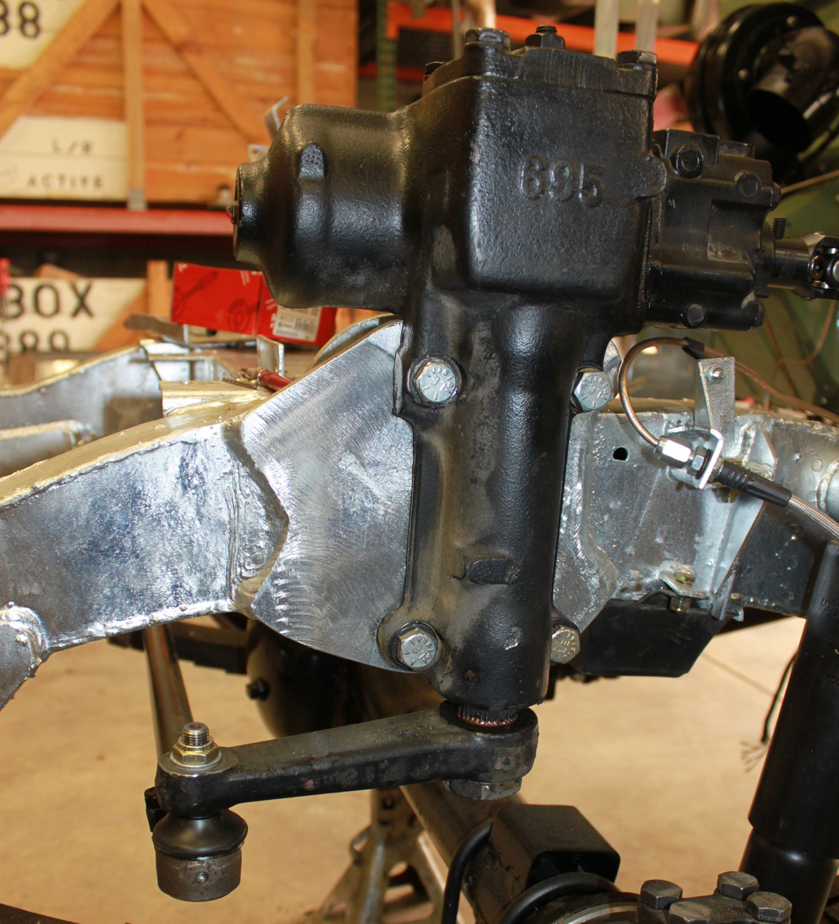
There are now two popular option for Series Land Rover power steering conversions. A conversion using the Scout II power steering box has been popular for a couple decades now. The conversion works very well and has proved itself as being trouble free and robust. However the Scout II power steering box was only offered as an extra cost option over a few years and they have become very hard to find. They were only available for LHD International Scouts. More recently fabricators have noticed that Rover finally produced a robust power steering box for the Range Rover P38 model and have begun to use them for Series Land Rover power steering conversions. As it turns out this is an easier conversion that using the more scarce Scout II power steering box in that you can make use of the Range Rover P38 steering arm without modification and the lower steering column. And, of course, the Range Rover P38 steering box is available in both LHD and RHD options giving people who live in RHD countries a viable option that does not include a hydraulic ram. The conversion procedure for both the Scout II and Range Rover P38 steering box conversions are basically identical except for the steering box mount on the frame. The P38 box has a longer vertical column and the top mounting bolts are farther apart from the lower pair of mounting bolts. The P38 steering box chassis mounting bracket needs to extend higher than the Scout II steering box and you should add an additional top brace for the bracket. The P38 conversion is simpler than the Scout II conversion in that you do not need to shop around for the right length of steering arm or ream out the small end to fit the angle of the Land Rover tie rod ends. Since I have already written this page for the Scout II steering box conversion and most of the guidelines are the same, I have added pictures showing the P38 power steering box mounted on a Series Land Rover chassis. Sorry I don't have dimensions of the adapter bracket but any fabricator should be able to quickly figure those out when they place the box against the frame. If you are doing a P38 steering box conversion I recommend first reading the Scout II guidelines then looking at the mounted P38 steering box pictures at the bottom of this page to see what the adapter bracket should look like. How to article from 1999 using Scout II power steering box belowThe Green Rover is one of a growing number of series Land Rovers that have been converted to power steering. The trend in the United States seems to be using the Saginaw steering box used in the late International Harvester Scouts. Bob Bernard was the earliest pioneer I know of to develop this conversion. He converted his 88, "Sherman" to power steering around 1989. Since then he has helped several other people make similar conversions. In the mid 1990's Timm Cooper independently concluded that the Scout power steering box would make an excellent box for a series Land Rover power steering conversion. Since then he has made several conversions and refined the conversion. What follows is what I have learned from both of these people and about the conversion performed on the Green Rover by Timm Cooper in 1999.
Parts:Steering box - The steering box used in the conversion comes from the Scout II. It has a unique mounting that lets it sit to the rear of the front cross member. Other power steering boxes require mounting in front of the radiator cross member. The Scout II steering box is fitted along the outside of the left Land Rover frame between the radiator bulkhead and the tab for the front brake flex hose. A mounting plate will need to be fabricated and welded to the outside of the frame rail. The box is available with two different sizes of input shaft. It doesn't matter which you use. Power steering pump - Most any power steering pump will work but the Saginaw "canned ham" type steering box that came on many GM cars and the Scout is highly recommended as being a very rugged, trouble free pump. Unless you have a GM engine installed a bracket will need to be fabricated to mount it to the engine. Engine crank pulley - You will need a two belt crank pulley. This was available on some series engines. Best bet for a series engine is probably from a company that specializes in ex-MoD Rover parts. Pitman arm - A Discovery I pitman arm will work on the Scout II power steering pump. The splines are the same as the Scout box (less the 3,6,9,12 keying), is the appropriate length, and is already tapered for a Rover tie rod end. Steering shaft - This is a shaft with a joint at each end that will connect the steering box with the Land Rover steering column. The overall length depends upon the exact placement of the steering box. So this is generally something that you get after the steering box is installed and the Rover steering column is ready. There are several ways to go. A collapsible shaft has a variable length so sourcing the exact length of the shaft is not critical. My car received a GM shaft probably out of a late seventies to early eighties car (It was already removed and sitting loose). There are companies that specialize in making up custom shafts from high quality parts & joints. A new shaft custom made for your application would be in the rough neighborhood of US$ 200. Hydraulic hoses - Many people end up reusing the power steering hoses that came on the Scout because they sourced the steering box and pump together. Depending on where you mount the steering pump the hoses are about the right length to a little long. The return hose is low pressure and held on with hose clamps. New power steering return hose is available by the foot at most auto parts stores. If you are lucky there is a hose shop or full service auto parts store that can fabricate a custom high pressure hose for you. There are a number of fitting possibilities. If your unit did not come with a high pressure hose go to a place that makes up power steering hoses with the steering box and have them match the box to a fitting part number. Then when you get the box and pump mounted and know how long the hose should be and if fittings should be straight, right angler or 'U' shaped, you know what the proper fitting type is. Other - you will need miscellaneous steel plates, bolts & bearings or a bushing depending upon how you choose to fabricate parts. Sourcing parts - You can get them used at a wrecking yard. A source for new Scout II steering box (seldom in stock anymore) and a heavy duty power steering pump is AGR Power Steering. If your plans include a MileMarker hydraulic winch, the AGR power steering pump should be your choice as it it pumps the maximum recommended pressure to the winch allowing it to operate at it's best speeds.
Mounting the steering boxThe steering box fits to the outside of the frame between the radiator bulkhead and the tab for the front brake flex hose coupling. This makes it virtually invisible to anyone who is not crawling around your Rover. Placement is as close as possible to the front brake flex hose tab. The tab ear that the flex hose connector normally goes to needs to be cut off. But the remaining part of the tab has an unused hole at the bottom just the right size for the connector. Using this lower hole actually gives you about two more inches of flex in the hose if you are lifting the body or increasing articulation with parabolic springs or by other means. The box fits against the remaining 'U' shaped part of the tab. You will find that the top of the steering box wants to sit on the top of the frame. Next you get to decide the amount of front to rear tilt the box gets. The more you tilt the vertical part of the box rearwards the less angle there will be on the steering shaft 'U' joints. However you quickly get into the space that the front axle uses when articulating upward. But tilting the box forward raises it as well making it less apt to be struck by the axle if you are doing gonzo offroading. Many people rest the box on the frame and do not tilt it. As a rule of thumb, steering shaft 'U' joints work and wear well at any angle less than 30 degrees and the axle can move forward a little when it articulates upward. Make sure the box stays out of the area where the axle housing may contact the rubber stop. Once you decide where you want the box, you are ready for the bracket. My conversion was done with the top of the box resting on the top frame rail and sitting almost up against the rear of the radiator bulkhead. Here are some pictures of different mountings showing different tilts: 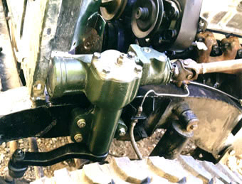
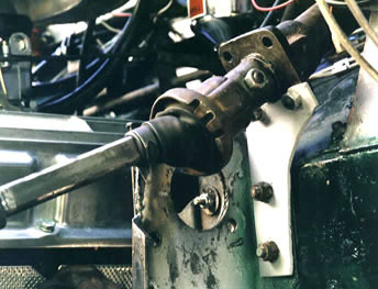
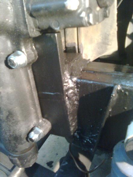
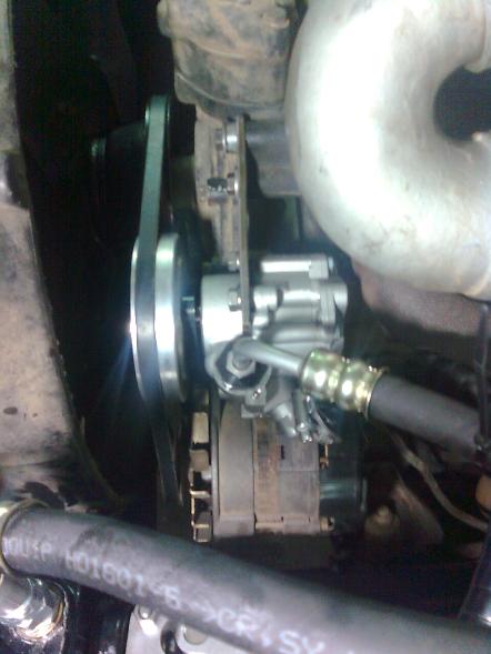
This is the steering box on the Green Rover. The top of the box is basically parallel to and sitting on the top frame. The vertical section of the box is well forward of the front axle's movement area. Note the 'U' joint angle on the steering shaft is well below the recommended 30 degree maximum. Also note the pitman arm. It is a Scout arm that was cut down in length, tapped and reamed to fit a standard series Land Rover tie rod end. You can also readily see the brake line relocated to the otherwise unused hole on the bracket. 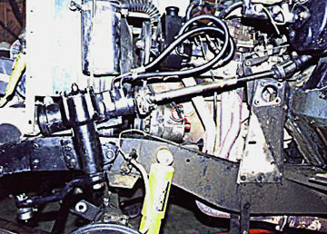
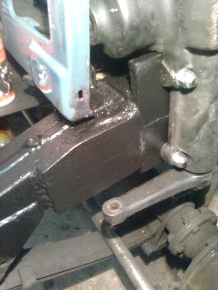
This is the power steering box mounted in Sherman, Bob Bernard's 88. Note that the box is tilted forward and sitting high enough that the rubber stop protects the bottom of the box from very extreme articulation. This straightened out the vertical angles of the steering shaft as much as possible. You can see the Saginaw steering pump mounted at the top of the 2-1/4L engine above the alternator. This picture shows a full length Scout pitman arm that was briefly installed. 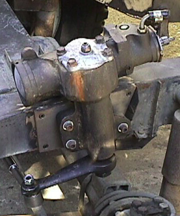
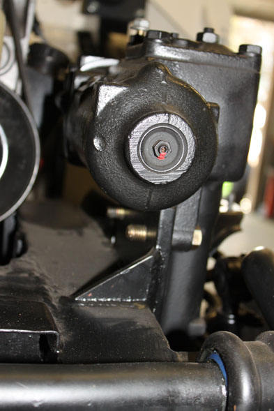
This picture shows another mount. This one is also tilted forward. It looks to be a little less tilted and a little lower. Note the GM pitman arm with matching GM tie rod end. This arm has hole centers 8-1/2 inches apart. Everyone seems to agree that the steering box mount needs to be stronger than the Rover's box frame. There are three mounting holes for the steering box. The front two holes are opposite the radiator cross member so a regular bolt will not do for the front. My mounting plate is made out of 3/8ths steel and has grade 8 nuts welded to the back. Clearance holes were drilled in the frame for the nuts. The plate was welded to the side of the frame. A bottom plate was welded underneath to effectively make an 'L' shaped mounting plate for additional rigidity where the box is mounted. 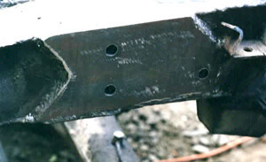
Mounting plate for steering box used on The Green Rover. Note the sideways 'V' cut in the front of the plate. This is to increase the length of the weld holding the plate on to increase the overall weld strength. Timm made a plate for his series I 109 using a 1/2 inch thick plate. He tapped the holes instead of welding bolts to the back.
Pitman armUse the pitman arm (steering arm) off a Discovery I. It does not have clocking so you need to get the steering box in the middle of its movement and mount the arm straight ahead.
Drag linkThe drag link is the rod that goes between the pitman arm and the steering arm on the right side. It will be too short for the new steering box. Purchase a length of hollow steel tubing that has an inside diameter equal to or slightly less that the outside diameter of the stock Rover drag link. You will cut off the ends of the old drag link and weld them to the ends of the tube. Fit the cut off ends so that at least an inch fits inside the new tube and weld them into place after you have determined the correct tube length. You may have to turn down the cut off sections of the drag link ends to get them to fit into the tube. When the pitman arm and front wheels are pointed straight ahead, the assembled length of the new drag link should be the distance between it's tie rod mounting holes with each tie rod screwed half way into the drag link. If you are using the Rover tie rod ends you just weld an end of the old drag link to each end. If you are using a GM tie rod end you can weld the end of the matching GM drag link to one end of the tube. A drag link has opposite direction threads at each end. This allows you to lengthen or shorten it by turning the rod while the ends are fixed. If you are using a GM end, be sure you use the Rover end that has the opposite hand thread to the GM end. It doesn't mater which end is threaded which direction as long as both ends thread in opposite directions.
Rover steering columnRemove the steering column from the Rover steering box. There are two schools of thought on this. one is to adapt a better suited non-Rover steering column and the other is o adopt the stock series steering column. If you decide to adopt the stock steering column, the worm gear will need to be cut off the steering shaft and a new GM section welded in it's place. This new section will attach to the GM steering shaft that connects the Rover column to the steering box. I was concerned about the resulting strength from welding two parts of a steering column together until I learned that the stock Rover steering shaft is made of three sections welded together. If you would like to go to an after market steering wheel to change the diameter of the wheel or different thickness wheel grip, you will need to use the later style plastic spoke steering column. There are no after market steering wheels currently available that fit the earlier banjo style steering column. The later plastic spoke steering column has a bearing to keep the top of the inner column in place. There needs to be a slight tension from the bottom end of the shaft to keep the bearing against the race. The older banjo spoked column used a bushing so a tension is not needed at the bottom. However it still needs to be clamped at the bottom to keep the steering wheel from being pulled upwards The lower part of the Rover column will need a bushing or bearing added to anchor the shaft in the column. One solution is to get a bushing that just fits the inner shaft and turn down part of the outer diameter so it only goes part way into the steering column. Another is to use bearings. The drawing below was made by Bob Bernard for the late style plastic spoked column. Click on it for a full size version. 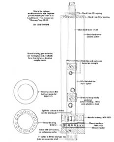
This drawing shows how Bob modified a late plastic spoke Land Rover steering column. It includes bearing and thrust washer part numbers. A bracket needs to be fabricated to hold the lower end of the Rover steering column into place. Mine was made out a small sheet of steel.
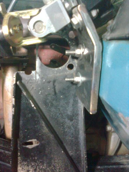
The lower steering column mounting bracket on The Green Rover. It utilizes existing mounting holes. Note the adjacent bracket that held the original Rover steering box. The flange had to be cut off for clearance. The lower end of the column should be anchored as close to the old mounting bracket as possible and have the steering wheel appear and feel straight. This is to minimize the horizontal angle on the top steering shaft 'U' joint. Also note the bolt going through the shaft above the upper 'U' joint. There are at least two kinds of mounts for GM steering shafts. The one describes in Bob's drawing above is splined. The one used on The Green Rover is round with flat opposing sides with a bolt hole to anchor the shaft into place.
Steering shaftThe steering shaft connects the Rover steering column to the Saginaw steering box. Collapsible shafts that expand easily along its long axis is the easiest to fit. There is normally a "rag" 'U' joint at the bottom connection to the steering box. This is to remove any vibration from the frame/box to the column. It wears out faster than a metal 'U' joint. You can use ether type. When you source a steering shaft you need to know which ends to get. The Saginaw box that came on the Scout had two different spline diameters. There are a couple of different upper mounts for the shaft as well. If you are adapting a used GM shaft, get the metal column rod that the shaft attaches to. You will cut off the bottom end of this and weld it to the bottom of the Rover column shaft. That will be the upper mounting point for the GM steering shaft. If you are having a company make up a custom shaft they will need to know how it connects at both ends. You might be able to get the connecting part that welds to the bottom of the column shaft from them. Remember a rule of thumb for steering shaft 'U' joints is to keep the angles below 30 degrees. Here are some pictures showing mounted steering shafts. 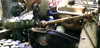
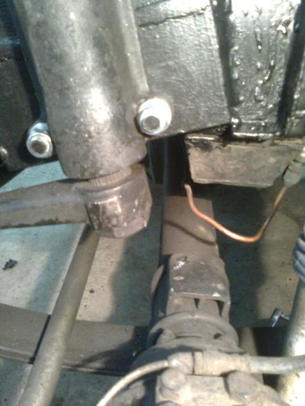
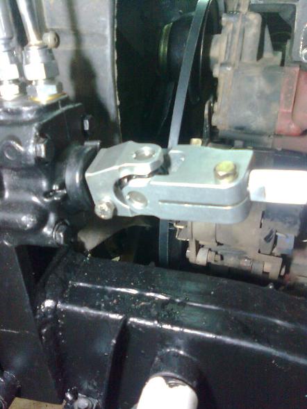
Here is the shaft mounted on The Green Rover. Note that it has a 'U' joint at the bottom and not a rag joint. The step in the middle of the shaft is where the upper half would collapse into the lower half in case of an accident pushing the frame & steering box rearward. 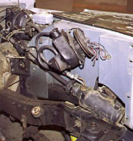
Here is a picture showing the shaft in Sherman, Bob's 88. The steering box is tilted to minimize 'u' joint angles. 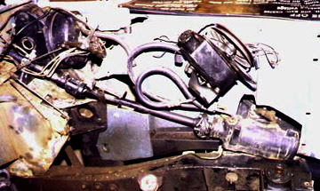
Here is the same instillation from a slightly different angle. If you look by the brake pedestal you can see that Bob places the steering column lower mounting bracket higher on the bulk head than Timm did for my Rover. You can also see the shape of the inner wing cutout for the steering box. Since the Green Rover's steering box sits lower the corresponding cut out is somewhat smaller.
Mounting the Power steering BoxIf you have a Rover four or six cylinder engine you will need to fabricate something from scratch. The pump should sit on the left side of the engine. Bob had his front left two head bolts modified to be used to mount a bracket. "I had two grade 5 bolts welded to the front left head bolts (removed from engine) This made them into mounting studs like GM engines use. I now need to torque these with a deep socket. Then with the pump in my hands, (I think this one was from 72 Pontiac with its brackets) I then used pieces of plywood cut to match cardboard that I fooled around with until it looked right, then cut and drilled pieces of steel to fit." If you have a GM engine in your Land Rover chances are very good that you can easily source a stock bracket to fit. If you have a Ford engine and decide to use the more dependable Saginaw "canned ham" style pump you will need to have a bracket fabricated. If you stay with the less reliable Ford style you will still probably need to get a bracket fabricated. Ford tends to put the power steering pump low on the left side. There would be a frame interference in the stock location.
And so...This should be enough to get you through a power steering conversion. I do not think that there is any exact correct way to do it. If you use the same basic parts, mount the box and pump in a similar way, stay away from the space used by axle articulation and don't make any steering shaft 'U' joint connections tighter than 30 degrees you should have a conversion that works fine. I know mine is a real pleasure when I need to make sharp turns a very low speeds.
Series Land Rover Power steering conversion using a
|
|
If you would like to discuss any of the contents, or just say hi, please feel free to .
© 1997, 2001, 2017 TeriAnn Wakeman. All rights reserved. |