|
The Smiths heaters available from the Land Rover factory before about 1968 were totally inadequate for Canadian and Northern United States winter weather. To address this a heater was developed for Land Rover North America by the Eton company in Canada. This heater was offered exclusively in North America as a dealer installed option starting sometime during late Series I production, continuing until around 1970 . There seems to be a few years during which the Kodiak Mk IV heater overlapped the Smiths fresh air heater. Almost all fresh air heaters used on series III Land Rovers were Smiths heaters installed at the Land Rover factory. Over the years there were four versions of the Kodiak fresh air heater which drew fresh air from one of three locations on the truck. They were the Kodiak MKI through MKIV. I have yet to pin down the years of manufacture but it appears that the Kodiak MKI was in production from around 1956 or 57 through 1958 or 59.Then the MK II was only in production for a year or two followed by the common MK III that was in production throughout most of the 1960's. The MK IV appears to have gone into production just before Land Rover introduced their fresh air Smiths heater. The Kodiak MKIV was manufactured by the Hupp Corp.,Mobile Products Division in Cleveland, OH. The Hupp Corp was formally the Hupp Motor Car Corp., manufacturers of the Huppmobile. The reason that the years of manufacture are so hard to pin down is that the heaters are a dealer installed option and each dealer had their own stock which got used until used up. So one dealer could still have MK I heaters in stock to install on a new Land Rover while another dealer may have run out of MK I's and be installing MK II heaters on the same year Land Rovers The heater was available as either a dealer installed option or as a dealer sold kit that an owner could retrofit onto their own Land Rover. As such there are some variations between vehicles as to how the heater was installed and some older Land Rovers were retrofitted with newer versions of Kodiak heaters. The Pangolin 4X4 web site does a good job of illustrating the different Kodiak air distribution ducting. Some people consider the after market Rovers North Mt. Mansfield heater to be the best heater upgrade so I thought I would give a BTU comparison. The Mansfield heater is rated at 20,000 BTU and the common Kodiak MK III is rated at 17,500 BTU. There is a 2,500 BTU difference between the two. Modern after market 4X4 heaters operate in the 25,000 to 28,000 BTU area but take a bit more effort to adapt to a Series Land Rover.
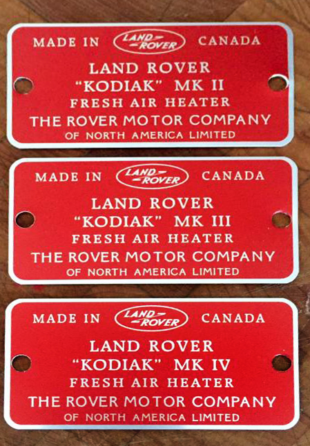
Badges
The Kodiak MK I heaterThe Kodiak MK I fresh air heater was introduced around 1956 or 1957 for the Series I Land Rover and used in the early Series II Land Rovers. These heaters draw their air from the front inner wing panel just forward of the radiator bulkhead.
The photos used to illustrate the Kodiak MK I are from a 1958 Series II Land Rover and are courtesy of Rich Lambert.
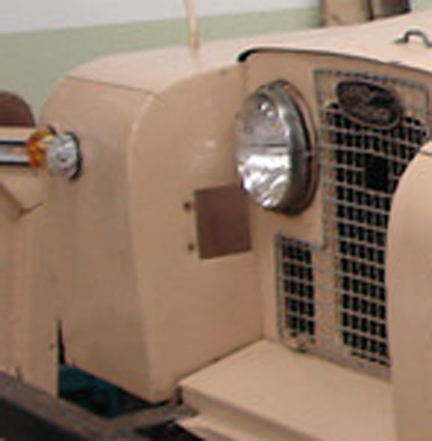
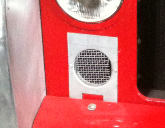
The Kodiak MK II heaterThe Kodiak MK II heater was only in production for a year or two. The fresh air intake is located on the lower right corner of the radiator bulkhead. The intake hole is fitted with a screen and hose mounting flange. The flange is held in place on the radiator bulkhead with two screws. The air intake hose is routed under the battery and air cleaner shelves to a heater core intake box on the right upper bulkhead. The series of Kodiak II heater pictures come courtesy of Mike Flahault. Taken while restoring his 1960 Series II Land Rover.
Thank you Mike for the use of your photos.
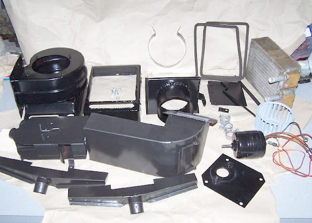
Kodiak MK III heaterThe Kodiak MK III heater was in production through most of the 1960's and is by far and away the most common version. The MK III is the first Kodiak heater version to draw fresh air from the upper rear section of the right outer wing panel. Previous versions drew fresh air from the front of the Land Rover. The Kodiak MK III heater produces 17,500 B.T.U/hour. The high speed of the two speed blower motor moves 190 C.F.M. A replacement fan motor for the Mk III and Mk IV is NAPA M882 Here are the spec sheet and fitting instructions for the Kodiak MK III:
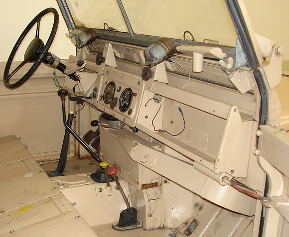
Control panel:Kodiak MK III control panel consist of three controls vertically arranged on a flat panel. The panel is flat metal, not the standard Land Rover accessory panel. It is 4 inches by 7 inches and has rounded corners. The panels are mounted at each corner by sheet metal screws that have both a slot and hex head. The panel is usually painted black. The holes for mounting the controls are "D" shaped to keep the controls from rotating. The look and mounting is completely different from any other of the Land Rover instrument panels. Since the heater is a dealer installed option and subject to dealer whims and customer preferences there are control panels mounted vertically on either side of the main instrument panel and horizontally to the underside of the panel shelf. There is no one correct location for the control panel. Controls:The layout of the controls from top to bottom are: Temp Control, Heater and Air Control. Temp Control - This is a wire pull that controls a valve located in the path of the coolant intake to the heater core. This regulates the amount of hot coolant flowing into the heater core and how hot the core will heat the incoming air. Heater - This is an electrical switch providing electricity to the squirrel fan's motor. This switch has two speeds. Extended to the middle detent the heater works at low speed. Extended completely the heater works at full speed. The switch has it's own fuse mounted on the switch body. The two speed function is designed into the switch and not the motor. Air Control - This is a wire pull that controls a butterfly valve in the path of the fresh air intake. It decreases the amount of air that the fan can blow over the heater core. This control allows you to close off this passage when the heater is off to prevent cold of dusty air from being blown into the interior as you drive.
Removing the control knobs:Removing the control knobs can be a frustrating experience if you do not remember how. The knob is held into place by pressure from a clip inside the knob pressing against the switch shaft. There is a hole in the side of the knob near the panel end. You need to get a fine rod and prise the clip off the switch shaft while you gently pull the knob off. Just pressing down in the hole will not work. I use a fine finishing nail and insert it diagonally against the base of the clip then lever the top of the nail towards the switch panel.  Heater switch:The two speed switch used in the Kodiak MK III heater is an American made part and should provide many years of service IF you keep the switch contacts clean. The switch was manufactured by the Cole Hersee company of Boston Mass. The two speed switch used in the Kodiak MK III heater has it's own 20 AMP BUS fuse mounted on the switch body. There are two wires going to the switch connected with bullet connectors. One wire carries 12 volts to the switch. The other goes to the blower motor. The switch slider has three positions. Retracted is off, partially extended detents are low speed and fully extended is high speed. The slider has three contacts. The middle contact is not connected to anything. The end contacts are connected to each other and makes electrical connections between both front switch body contacts or both middle switch body contacts as shown in the switch wiring diagram.
The switch body contacts are mounted into a fiber board. If the contacts become corroded they will overheat and burn away the edges of the fiber board holding them in place. This allows the switch contacts to move away from the slider contacts. When this happens the heater stops working. I have had success disassembling the switch and epoxying the contacts back into the fiber board. This must be done carefully to prevent further damaging the board. The contacts need to be properly placed for drying. Prevention is easier than fixing. It is a good idea to periodically clean the heater switch contacts with a good spray contact cleaner while moving the switch shaft in and out. If you can keep the contacts clean the switch should remain in good operating shape. If your switch is toast, there are a number of plug and play 2 speed heater switches that will do the job. Check companies that offer restoration parts for 1960's American cars.
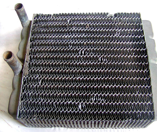
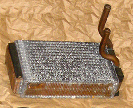
Kodiak MK III pictures:Kodiak MK III heater core
The core itself is 8 inches by 8 inches by 2-1/2
inches thick
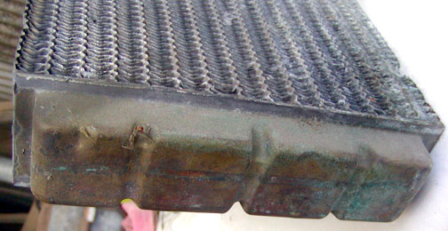
The inlet tubes are 1/2 inch dia and 4-7/8ths inches apart centre to centre.
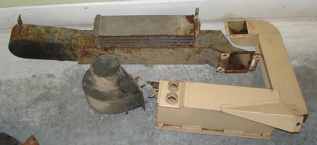
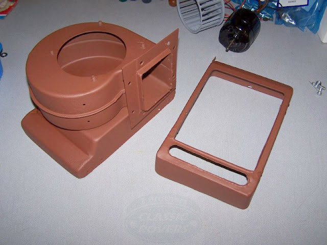
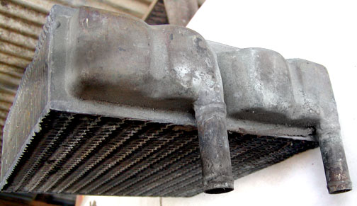
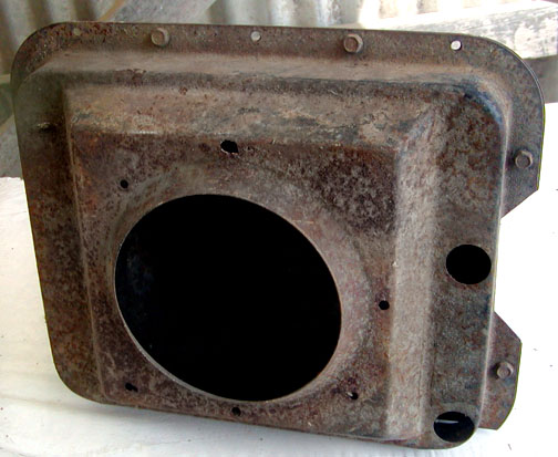
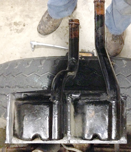
Kodiak MK III heater core housing:
The housing site with the core vertical and the metal tube facing the hole in the right wing. A flap valve sits inside the tube to control inlet air flow.
This is the side the fan attaches to. The inlet openings are parallel to the bulkhead and can be difficult to get to when removing old stuck on hoses. Sorry no picture of the fan yet
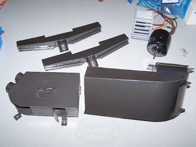
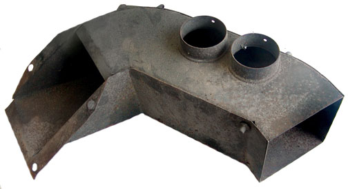
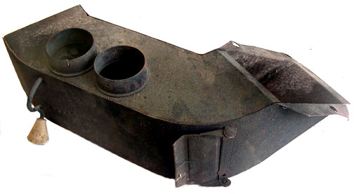
Kodiak heater MK III air distribution box
The inlet for the heater air distribution box is the bulkhead hole for the right hand side brake pedal. With luck the dealer enlarged the hole to the size of the inlet. If not you can get additional air flow by doing so.
The lever deflects the air to the windscreen when horizontal and to the driver's legs when down. There are bumps in the side of the box that allows the lever to be set part way open. The flap door provides hot air to the passenger's legs. There is a permanently open vent on the underside that vents hot air to the passenger's' feet.
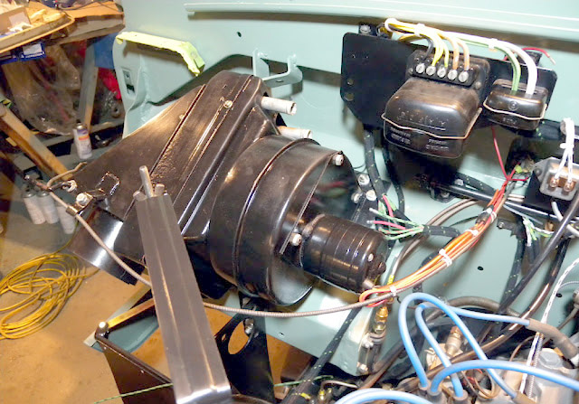
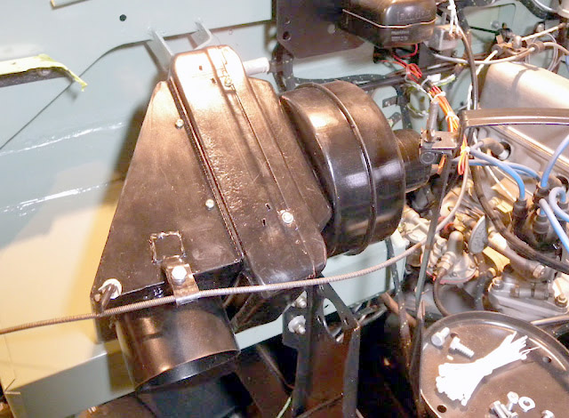
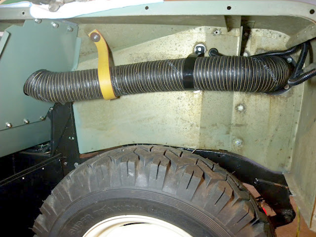
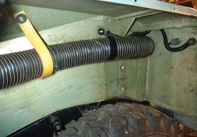
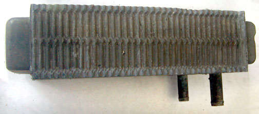
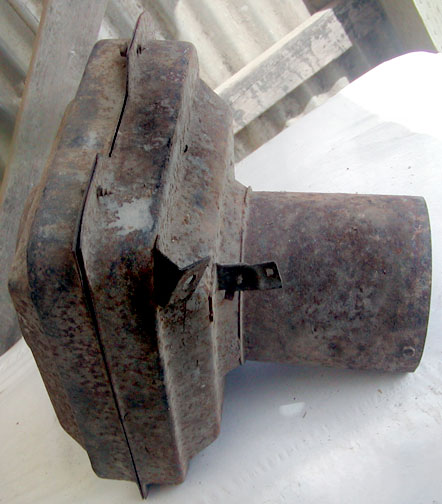
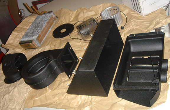
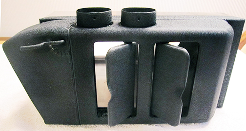
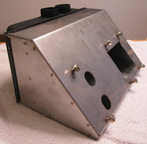
Kodiak MK IV heaterThe Kodiak MK IV heater was only in production for a brief time before the Smiths fresh air heater was introduced. Unless noted MK IV pictures courtesy of Joseph Miner.
The intake house is routed to the radiator bulkhead inside the engine compartment.
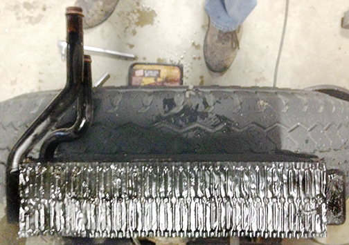
Kodiak MK IV heater core The core is 10”x6”x2.5” with one side having a single side tank of 5.5” x 1 7/8” x3/4”
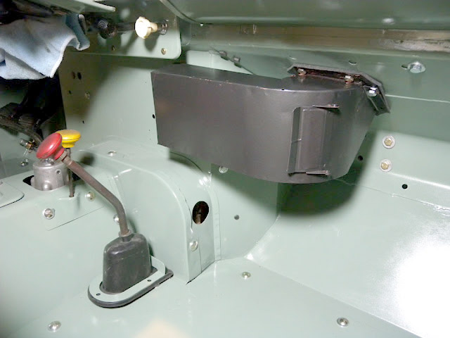
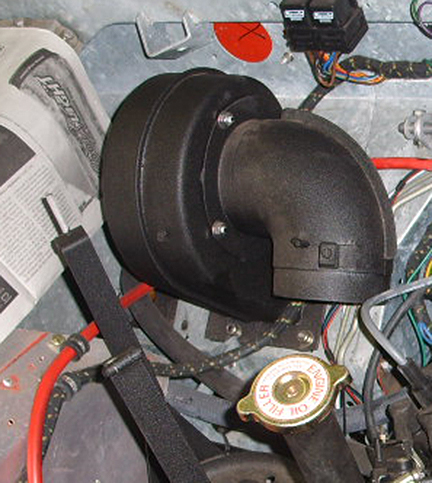
Maximizing heat:A heater works by air flowing through a hot core then into the car's interior. Anything that lowers the heat of the coolant or decreases the coolant flow lessens the amount of heat a heater core can produce. Anything that reduces the airflow cuts back on the volume of heated air flowing into the car interior. Poor condition or missing door seals and other outside air leaks counter the hot air from the heater. Adding insulation and making seals more effective helps keep the heat in and the cold out. The blower is mounted on the bulkhead above the hole for the right hand drive clutch pedal opening. The cover for this clutch pedal is removed to allow air from the blower to pass into the car's interior. Some installers cut the hole open to match the fan ducting while others just used the existing narrow opening. The clutch pedal opening is much smaller than the fan housing opening and restricts the amount of air that the fan can push into the interior. If you are trying to maximize heat you need to check to see if the bulkhead opening is the correct size or restricting the fan's air flow. If the hole is the pre-existing narrow clutch opening you get a large increase in heater flow by matching the hole in the bulkhead to the fan duct hole The Kodiak heater will not work efficiently unless the core is clean both inside and out. Particles can deposit inside the core and build up to the point where back flushing will not loosen them. If everything seems to be working and you are not getting enough heat remove the core and take it to a radiator shop to be boiled out. The operating temperature of your engine not only affects it's operating efficiency, it also affects how much heat your heater can produce. In cold weather conditions going to the "winter " 180 degree thermostat makes a big difference in the amount of heat a heater can produce. A radiator muff helps keep the operating temperature up when the outside air is too cold for the engine to normally reach operating temperatures. The warmer your engine runs, the more heat your heater can produce. The incoming air is cooling the heater core and the coolant is keeping it hot. The coolant flow must be high enough to keep the heater core as hot as possible. The heater coolant valve not only restricts the amount of coolant available to the heater core it can also get stuck partially open further decreasing the amount of heat available to the core. A heater coolant valve that does not get exercised frequently tends to become stuck at whatever setting it has been sitting at. I have removed my valve completely to maximize coolant flow into the heater core. Remember, a warm engine producing a good flow of hot coolant through a clean heater core is the primary key to maximizing the amount of heat your heater produces. The output of your heater is in competition with the outside ambient air temperature. Bare aluminum is an excellent thermal conductor. Insulating your car can make a big difference on how warm the interior of your car will get during cold weather. The cold air flowing in through seal and body gaps counter the hot air from your heater. Effective seals can go a long way towards keeping your Land Rover's interior warm. If your seals are worn and deformed consider new ones. Do NOT use the factory "genuine" door and scuttle vent seals made for Series Land Rovers. The company making them for Rover is making them slightly too large. You will have a very difficult time closing the scuttle vents and you will almost never be able to train the leading edge door seals to fold down properly. Defender scuttle vents work better on the series LR than the genuine series ones do. The same is true of door seals.
Recommended preventative maintenance:There are a few things that you can do to keep your heater in good operating condition. I suggest disconnecting the heater coolant hoses at the engine and flushing the heater core with a hose at least once a year. This will clean out the sediments before they get a chance to compact and require professional cleaning. At least once a year clean the contacts of the heater switch. Dirty corroded contacts create high resistance connections and generate heat. This heat can destroy the fiber board that holds the switch contacts in place. Exercise the temperature and air controls a couple of times a month to keep them from "freezing" in place. At least once a year visually inspect the heater and hoses. Clean and replace as necessary. If you decide that the hoses going between the engine and heater core need replacing I strongly recommend that you cut them off the heater core tubes. These tubes are made of soft brass. Gripping them with pliers and twisting frequently results in deformed tubes. Deformed tubes are difficult to seal and can be very difficult to straighten without removing the core. It has been my experience that most Kodiak heater core leaks are really leaks around deformed tubes where the clamps do not seal the hoses. The interior heater ducting usually has a small door that can be opened to blow hot air onto the passenger's legs. The hinges can rust into place. If you use the vent with rusted hinges the metal around the hinges will bend and fatigue causing the door and hinges to fall off. It is a good idea to use a light penetrating oil on the hinges a couple of times a year and exercise the hinges to make sure that they work properly.
|
|
If you would like to discuss any of the contents, or just say hi, please feel free to .
© 1997, 2001, 2017 TeriAnn Wakeman. All rights reserved. |