|

Converting to a Delco 3 wire alternator
When I was moving from Seattle to Monterey I took the costal route in my 1968 Land Rover 88. It rained when I left and for the length of Oregon. One thing I learned on that trip was that my factory generator could not keep up with a couple days of driving with headlamps on, Kodiak heater on high and the 2 speed wipers going on fast. By the third morning there wasn't enough juice left in the battery to start the engine.
A lot of Series Land Rover folks have learned that lesson over the years, and many more have added electrical components such as auxiliary lighting, radios, heated windscreens and electric fans that draw even more electricity. There comes a time when you decide the old generator just doesn't do the job of keeping your battery fully charged while you run the vehicle. You start asking around and everyone tells you to get a Delco 3 wire alternator with a built in voltage regulator. Suddenly you find yourself wondering what they are all about and how to hook one up. That's what this web page is all about. A quick primer on the Delco 3 wire alternators commonly used on Land Rover conversions and how the charging system is connected.
I'm afraid that what this page will not do is tell you how to remove the stock voltage regulator from the circuit and have everything still work. It is doable by keeping the regulator in place, moving some wire connectors and adding a jumper wire or two but I've never done it. When I converted to an alternator I ripped out the poor condition many time spliced wiring harness and made my own from scratch. So you will still have to research that part. There is a lrfaq web page that goes over how to make the conversion of a factory Series Land Rover harness to three wire alternator. If you are installing a new wire harness at the same time as you are converting to an alternator, I understand that you can special order a Series wire harness for an alternator with built in voltage regulator from British Wiring. It should save you a lot of work.
Ammeters & voltmeters:
The 30 amp ammeter on your Series Land Rover's instrument panel can easily spend time pinned and burn out with a 60 amp or higher powered alternator. They work OK with the lowest rated 37 AMP 10-SI alternator but you will need to scare up a 60 amp gauge for the up to 60 AMP alternators. Your easiest and best solution is to remove the ammeter, connect the + and - wires together and install an automotive voltmeter between switched 12V and ground. An ammeter will tell you if the vehicle is getting its load from the alternator/generator or battery, how much the lcurrent draw is but not much else. A voltmeter will tell you the if your alternator/generator is putting out enough voltage to keep up with the load and still keep the battery charged. With an ammeter you can have a generator that is not quite keeping up with the load and slowly draining your battery. Things can look fine but one day you find your starter motor barely turns. A voltmeter alerts you to any charging problems or an unusual load overwhelming the alternator immediately. It will tell you if your alternator is overcharging or undercharging and just the overall health of your charging system. I suggest that you just ditch the ammeter and replace it with an automotive voltmeter.
Alternator placement:
If you plan to relocate the alternator when you mount it, the best place is to mount it high (to keep it away from the water while wading) and as far away from the exhaust manifold as practical.
The alternator cooling fan is actually an EXHAUST fan, which draws air into the alternator from the back through the rear air vents, past the rectifier heat sinks and out the front housing, The worst place you can mount an alternator is next to and directly in front of the exhaust manifold.
If you are converting a Series Land Rover equipped with a 2.25L petrol engine from generator to an alternator you will need to replace the generator mounts with new alternator mounts. You can weld up some custom brackets, search wrecking yards for something that may be made to work or you can just purchase a set specifically made to mount Delco 10-SI alternators to a Series four cylinder engine. These brackets are made by Pangolin 4X4 specifically for this application. It puts the alternator up high, away from water splash and away from the heat of the exhaust manifold. An excellent solution that is well worth the price. The stock location can put the alternator under water when wading and has the air intake for alternator cooling near the exhaust manifold. Ike, of Pangolin 4X4 wanted me to mention that alternators clocked in the 12 O'clock position work best with his adapter and the alternator brackets require a spacer when used with aftermarket headers because the flange is so much thinner than the stock manifold.
Not all Delco alternators are the same:
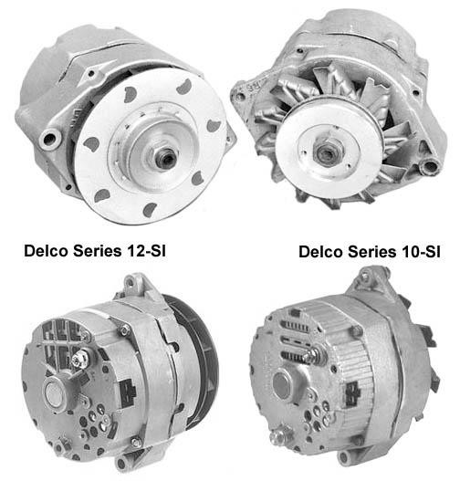
The Delco 10-SI or 12-SI series are the ones you want to get. Pick the one that produces more current that your truck draws with everything turned on. But realize that AMP ratings costs money so you save money by nor immediately jumping on the 94 AMP 12-SI alternator. As a rule of thumb, the common 60 AMP 12-SI were used on carberated vehicles. I've found they can handle EFI, headlamps, and a heater but not electric raditor fans on top of EFI. If you have EFI and electric radiator fans you will need to 94 AMP version.
The Delco 10-SI alternator with internal regulator replaced the lower power output Delco DN series which used an external voltage regulator.
10-SI Series alternators were introduced in the early 1970’s and are available in 37, 42, 55, 61, 63, 70 and possibly 85 Amps. The 61 amp size was very common on cars with a V8 and air conditioning. And it is roughly twice the output of the generator that came on your Land Rover. 10-SI alternators with higher than 63 amp output tend to have a larger housing which may cause fitting issues. The 10-SI series is easily recognizable by the Rear 3 air vent holes and the old style stamped steel fan. The Delco 10-SI alternators tend to be less expensive than the 12-SI alternators.
The Delco 12-SI series was introduced around 1983 phasing out the 10-SI series.The 12-SI series alternator is easily recognizable by the six rear air vent holes and a plastic water wheel style fan, The extra vents and new fan design provided better cooling and allowed higher amp ratings. These were available in 56-amps, 66-amps, 78-amps, and 94-amps. Of these the 78 amp size was most commonly used and might be your least expensive option. The 12-SI alternator housings are basically the same size as the common 10-SI housing.
The Delco CS-series alternators replaced the 12-SI series alternators. These look completely different and generally come with a serpentine belt pulley. The wiring for the charging system is completely different and a bit more complicated than the SI series circuit. CS series alternators are supplied in 61, 70, 72, 74, 80, 85, 96s, 99, 100, 102, 105, 108, 124, 140 and 145-amp configurations.
Finding a rebuilt alternator
Most auto parts stores have terminals that have information which is only accessible by part number or by vehicle year, make, model and engine size information. These tend to be operated by poorly paid, relatively inexperienced people who generally can not help much if any unless they can extract information from the terminal. So either you need to pretend that you have a certain vehicle or have a number that they can look up. They will not know about 10-SI or 12-SI series of alternators, AMP ratings or anything unless you get al old timer parts person in an independent shop who knows off the top of his head what the hot rodders use.
There is a company called Lester that produces automotive catalogues that are the standard for the American automotive parts industry. Interestingly just about everyone can reference Lester part numbers. Autolite rebuilt alternators even use the Lester part number with a couple letters on each side. So someone can search a shelf of Autolite rebuilt alternators and find a certain alternator just by knowing the Lester number. Frequently the Lester alternator number will have a dash 3, 6, 9 or 12 behind it. That indicates the clocking of the back and where the molex plug sits in relation to the alternator mounting point used to tighten the fan belt. 12 o'clock means the molex socket is lined up with the mounting tab. The others are located by assuming you are looking at the rear of the alternator. GM tends to place their alternators on the right side of the engine so the molex connector is most commonly located in the 3 O'clock position with the 12 O'clock position being the second most common position.
Some parts houses can look alternators up by the Lester number with a -3, -6, -9 or -12 to find the version clocked for your application.
Here are some popular Delco alternators by Lester number and vehicle descriptions:
SI Series |
Amp rating |
Molex plug
clocking |
Lester number |
Delco number |
Vehicle |
10 |
63 |
3 |
7127 |
321-143 |
1978 Cultlass Supreme, 260 V8 |
10 |
63 |
3 |
7127* |
321-39* |
1984 Chevy Camaro, 305 V8,4BBL
1978 Chevy Camaro, 350 V8, with air
|
12 |
78 |
3 |
7273 |
? |
1985 Buick Century Custom, V6 |
12 |
78 | 3 |
7278 |
321-357 |
1986 Buick Regal 307 V8 |
12 |
78 |
9 |
7278 |
321-244 |
1985 Oldsmobile cutlass Suprime, 307 V8 |
12 |
94 |
3 |
7294 |
321-266 |
1984 Chevy Camaro 305 V8 |
12 |
94 |
9 |
7294 |
321-269 |
1985 Buick Riviera, 307 V8 with air |
10 |
40 |
|
7176 |
|
24V alternator |
* The 7127 / 321-39, 63 amp alternator is a very common inexpensive alternator that just about everyone keeps on the shelf and is a good choice for most Series Land Rovers.
It has been the choice of hot rodders with carburatted engines for a couple decades because it is cheap, easy to come by and works well. Fuel injected engines with electric fans usually should go to a higher rated alternator. But for most conversions this is the one you want.
If you have information for other 10-SI or 12-SI alternators, please email me with the information so I can add it to this chart.
Clocking an SI series alternator:
If the molex connecter is located in a less than optimum location for your set up, the back of the alternator can be rotated to put the molex connector in the optimum location. This process is called re-clocking an alternator.
Clock position of the SI series of alternators is determined by viewing the alternator from the rear, with the threaded mounting hole straight up (the 12 oclock position). The two pin connector can be located in any one of 4 positions; straight up (12 o'clock), 90 degrees to the left (9 o'clock), straight down (6 o'clock) and 90 degrees to the right (3 o'clock).
The alternator rear housing is bolted to the front housing with four bolts. The two housings have alignment slots located at every quarter turn position. You remove the bolts holding the two housings together then very carefully move the halves apart just enough to unhook the alignment slots so you can rotate the rear housing. Rotate the rear housing to the desired molex plug location, align the lots then push the housings back together and bolt them back together. If you pull the housing halves too far apart the brushes will come off and you will need to separate the halves to reapply the brushes. If you are hesitant to re-clock the alternator yourself your local automotive alternator/starter motor shop and easily do it for you, usually at minimal cost.
Batt |
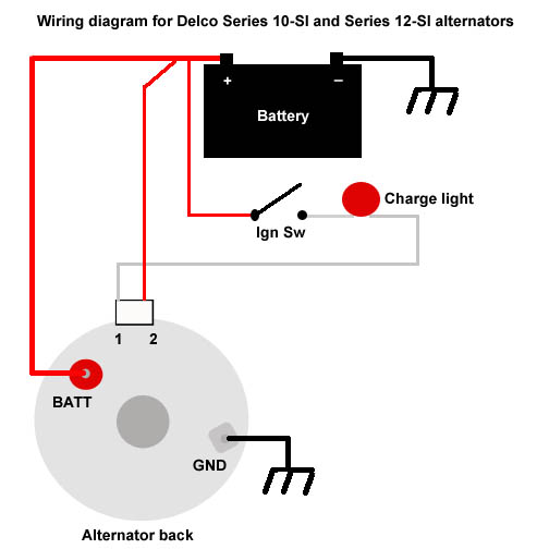
(Brown AWG #10 or #8 wire going to insulated terminal at rear of alternator) This terminal is for the alternator output to the battery. On Land Rovers equipped with an ammeter this lead goes directly to the ammeter POS terminal. The ammeter NEG side goes to the battery positive terminal, usually by being connected to the starter switch or relay. A 10 gauge wire will work for all the 10-SI alternators and the low to mid amp 12-SI alternators. The high amp 12-SI should get a AWG #8 wire. You should install a fusible wire link in this wire in case of an accidental short to keep the shorted wire connected directly to the battery from starting a fire. The fusible link should be placed near the battery. Brown wire if installing in a British vehicle, red wire if installing in an American vehicle. In the UK, brown is the standard colour for a wire that is always hot and unfused. |
1 "Excite" |
(White AWG # 14 or #16 wire on white molex plug) This wire provides the start up voltage for the alternator. The "1" alternator terminal is fed by a switched 12V source from the ignition switch through a lamp ("idiot light") and is used to supply the magnetic field inside the alternator with the voltage needed to operate. The alternator can not start charging until there is a voltage on the field winding and a magnetic force is created.
The “idiot” light is there to act as a visual indicator of under voltage and over voltage conditions at the battery. When the engine is running, if the idiot light is on, the output voltage of the alternator is out of specification. |
2 "Sense" |
(Red AWG #10 or #12 wire on white molex plug) The 'Sense' wire checks the voltage output level of the alternator. This is the reference voltage that the alternator uses to determine how much power to put out. If the sensed voltage gets higher than the regulator is adjusted for, the regulator causes the alternator to momentarily stop charging until the sensed voltage drops down to a specified amount, then the alternator resumes charging. The regulator basically turns the alternator on and off fast enough to keep the output voltage within a specified voltage range.
The Number two "sense" terminal is often connected to the BATT. terminal at the back of the alternator. This is the simplest connection and the least desirable since it is measuring the alternator output and not the voltage at the load connections. Any voltage drop due to loose, dirty or corroded connections and internal resistance of the wires and components is not accounted for and the voltage at the circuit loads may be lower than it should be. The voltage is best sampled in the interior of the vehicle after the fuse block load, where all the electrical current load of the vehicle is. The 'Sample' would better sense a voltage drop and and the alternator would correct for it.
|
Gnd |
(Black AWG #10 or #8 wire going to screw on back case of alternator) When most people convert to a SI Series Delco alternator they leave off the ground wire and rely upon the alternator mounting bolts, engine block and engine to ground strap for an alternator return path. This works just fine most of the time as long as the mounting bolts are making a good electrical connection. Sometimes the ground connection may not be all that good or it may get worse over time. This higher resistance connection keeps the alternator from generating its full rated amperage. An AWG #10 or #8 gauge wire between the alternator ground connection and a good frame ground assures a good pathway for the alternator. This wire should have a fusible link in case your engine to frame ground strap fails and tries to route all the starter current through the alternator ground wire. |
Some common fault symptoms and what they most likely indicate:
- AM radio interference, bad rectifiers.
- Battery discharges overnight, bad rectifiers
- Charging voltage below 13V above 2000 engine RPM alternator likely not working. Pull alternator and take down to shop to be tested.
- Idiot light does not come on when key on and engine not running, bad bulb or electrical connection.
- Stop vehicle & check immediately If not belt look for a connection that just came off. Your alternator has stopped charging. If nothing obvious can be found, pull alternator and have it checked on a machine.
- Idiot light on very dimly. Alternator charging but not enough to keep up with current drain produced by vehicle electrics.
The most common charging problems are caused by poor connections, especially poor ground connections. Be sure to check all your connections. If you are using crimp connections be sure to inspect the crimp for connector and wire oxidation.
Return to page top
|