|

Wiring up a 200tdi after transplant into a Series Land Rover
By MWS1967 on the Series II club forum
OK I think I have sorted the engine wiring out including the glow
plug timer.
Alternator connections
Assuming you are using the disco alternator. The terminal
B+ can go to the battery positive or to the starter motor (thick
brown/red wire) The terminal D+ goes to the dashboard warning
light (brown with light yellow stripe on disco wiring). The terminal
marked W is for a diesel rev counter.
Starter and charging circuit
Assuming you have the glow plug timer and its associated plug with
wires coming out.
First looking at the wiring diagram :
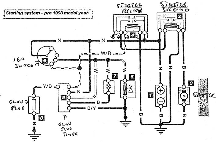
1 = battery |
4 = 5 pin relay |
7 = cold start light |
2 = Starter Solenoid |
5 = fuel shut off solenoid |
8 = no 1 glow plug |
3 = Starter |
6 = Ignition Switch |
9 = Glow plug timer |
Ok here we go –
Ensure that the thick red or brown battery live/positive wire
is connected to the started motor solenoid and that the starter
motor earth wire is connected to the engine block; also ensure
that the engine is earthed and that the battery has an adequate
earth going to the bodywork. The original ignition switch feed
from the battery should also be reinstated – this should
hopefully be clear from the wiring diagram.
- The white/red wire from the ignition switch which normally
goes to the starter solenoid to actuate it to turn the engine
over should be connected/spliced to the white/red wire on the
glow plug timer wiring. This wire then connects to terminal no
86 on the five pin starter relay.
Terminal 86 is the terminal that triggers the starter relay when
fed a current.
- 2 Connect a wire of appropriate rating from the spade
terminal on the starter motor solenoid to terminal no 87 on the
starter motor relay. Terminal 87 is the output terminal that
outputs a voltage when the relay is triggered.
- Connect a wire from terminal no 85 on the starter motor
relay to earth.
- Connect a wire from the battery positive/live to terminal
no 30/51 on the starter motor relay. Terminal 30/51 is the input
on the relay and outputs through terminal 87 when terminal 86
is triggered.
- The thick yellow/black wire from the glow plug relay
goes to no 1 glow plug.
- The thick brown wire from the glow plug relay goes
to the battery positive feed.
- The white wire from the glow plug relay splices in
to the white wire from the ignition switch and goes to the cold
start warning light and to the fuel shut off solenoid.
- The black wire goes to the earth side of the cold start
warning light.
- The black/yellow wire goes to the earth side
of the fuel shut off solenoid
Return to page top
|