|

Converting a Series Land Rover 109 to a Land Rover 200 Tdi engine
By Glen Anderson
My 200TDI install… For anyone who’s interested!
Notes: Glen has installed a 200 tdi
from a Discovery into his 1959RHD 109 Series Land Rover. Glen
carfully documented his progress to help others contemplating
this conversion. All
text and pictures copyright 2007 by Glen Anderson.
As has been discussed at great length on various
Internet forums, Land-Rover’s 200TDI is possibly the best
current option for an engine upgrade in a Series vehicle. The Discovery
and Defender units, whilst based on identical blocks and heads
have several major differences in the layout of their ancillary
components.
For those of us planning on putting a TDI into a Series vehicle,
probably the biggest difference is the layout of the timing covers.
The Defender cover is the same as fitted to the 2.5NA and 2.5TD
engines and, as a consequence, the fuel injector pump is mounted
low down on the driver’s side of the engine. This fouls the
Series engine-mounting bracket. To use the Defender engine-mounting
bracket requires chassis surgery on the driver’s side chassis
mount. The Discovery timing cover, however, mounts the injection
pump high enough to clear the Series engine-mounting bracket and
allows fitment without chassis modification (although you do need
to re-site the battery tray and battery).
As I have a galvanised chassis under my 109” I was reluctant
to carry out any welding on it so I sourced a second-hand Discovery
engine and ancillaries via the dreaded ebay. Discovery engines
are also currently more plentiful and therefore cheaper, which
is a bonus!
First job was to remove the Discovery engine mounts. These were
replaced with Series items. On the passenger’s side there
are two sets of mounting holes – use the front set.
Next job was to address the gearbox mounting area. All the studs
on a TDI are metric, M10 to be exact. These are fine, but their
17mm spanner size nuts can be awkward, especially around the clutch
slave cylinder bracket. You need to source four additional studs
for the area around the bottom of the housing. It is possible to
source 15mm spanner size M10 nuts for the awkward areas and retain
the metric studs, but I had a pack of Series 3/8” studs and
a 3/8” UNC helicoil kit – so I decided to replace all
the M10 studs with “proper” Series’ ones!
Most of the original M10 studs are in exactly the right place.
One of them, on the driver’s side of the housing, needs removing
though.
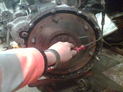
This is the stud you need to remove.
The housing, very conveniently, has blind holes in all the rest
of the locations needed to match up with a Series gearbox. I simply
tapped these out to 3/8”UNC. The standard TDI set-up uses
four long M10 bolts at the bottom which go through the gearbox
bellhousing, flywheel housing and secure into the sump/block stiffener.
Most people seem to advocate ignoring these, as earlier engines
don’t have them. I reason that Land-Rover felt they were
needed – so rather than leave them out I counterbored the
housing with a 16mm drill to give clearance for some socket-head
cap-screws (Allen bolts if you prefer). M10x75 were perfect, and
sit just below the mounting face of the housing. There are also
two dowels, at about two o’clock and nine o’clock as
you look at the rear of the housing, which need to be pulled out – a
pair of mole-grips did the trick for me.
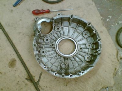
Housing with new studs and four bottom holes counterbored.
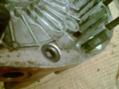
Allen bolt in counterbore.
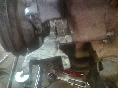
A final task was to offer the housing up to my spare gearbox’s
bellhousing. This trial fit confirmed the studs were all in the
right place, but revealed the necessity to relieve the housing
slightly to allow it to sit snug against the gearbox. Each of the “bulges” in
the housing that holds (or held) a stud needed relieving about
1-1.5mm. Once this was done, and a further trial fit confirmed
all was well, the housing was refitted to the engine with a new
housing to block gasket and crank oil seal. The flywheel then went
back on.
Whilst we are at this end of the engine it’s worth mentioning
that the standard Series IIA diesel spec 9.5” clutch pressure
plate (part number 571228) and friction plate (FRC2297) will bolt
straight on to the TDI flywheel and mate with the Series II/IIA
gearbox. If you are using a Series III gearbox then you can either
use a standard Series III clutch, or the TDI pressure plate with
a Series IIA/III friction plate.
In order to avoid a complicated and tortuous exhaust header pipe
I tracked down a set of Defender inlet and exhaust manifolds. They
weren’t cheap, but they will allow a much easier routing
of the exhaust header. Unfortunately, they do mean that the standard
Discovery high mounted alternator was going to foul the new Defender
inlet manifold. As standard, the Discovery engine uses one belt
from the crank to drive the waterpump and power-steering pump,
with a second belt from the power steering pump then driving the
alternator. As I had no intention of using the power steering pump,
and needed to resite the alternator, I had a bit of a measure up…
The solution I ended up with uses a pulley sourced from an early ‘90’s
Volkswagen Jetta/Golf on the standard Discovery alternator – this
puts the “V” of the pulley approximately 12mm further
forward than standard. I then made up two 12mm spacers to fit between
the block and a standard Series III alternator bracket. This then
placed the alternator pulley exactly inline with the crank and
waterpump pulleys. By happy coincidence the original power steering
belt fitted (although the next size up would be a bit better) and
the Discovery alternator-adjusting strap was re-sited off one of
the timing cover bolts.
Series III alternator bracket and 2x12mm spacers.
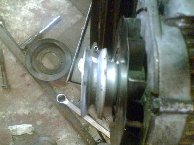
Discovery alternator with Volkswagen pulley.
View from above, showing pulleys all in alignment.
Front view. Drive belt is standard 200TDI Discovery power steering
belt.
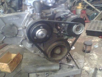
Another mod carried out in this area was to swap the alternator
from one “hand” to the other – this is simply
done by removing the 3 long bolts securing the front and rear casings
together and turning them 120 degrees relative to each other, so
that the rear mounting lug lines up with the other front mounting
lug, and then reassembling. The alternator is a standard Lucas
A127 55amp unit.
You can also see from the picture that the thread on the nose
of the waterpump has been removed to allow greater clearance between
the pump and radiator. An electric fan will be used instead of
the viscous unit.
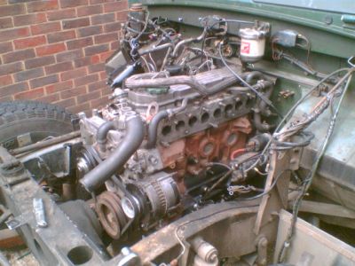
The next step is fitting the engine into the chassis.
Normally, when swapping an engine, I would only remove the bonnet
and radiator. This time, however, it made much more sense to remove
both front wings and the radiator panel as well to make sure I
had enough room both to work, and to see and trial fit the additional
TDI ancillaries.
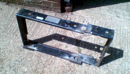
Some careful measuring prior to attempting to fit the engine had
confirmed that it was definitely going to be necessary to modify
the standard, Series style, battery carrier. The injector pump
on the TDI fouled the inner rear corner, and my intended radiator-fitting
site fouled the inner front one. As removing both of these was
going to leave the rest of the assembly very wobbly I decided to
remove the whole thing. I have left the two outer “tags” about
2/3 of their original length as, maybe, they might come in handy
at a later date. On the next page is a picture of the chassis minus
it’s battery tray.
With no obstacles now to physically getting the engine into the
chassis, that was what I did!
The driver’s side engine mounting (that’s the RHS,
looking from the rear of the engine) needs to be assembled, complete
with the rubber mounting bobbin and bottom plate, before it’s
bolted to the block. Otherwise there is just not enough room to
get a spanner in beneath the injector pump to do the bolts up.
I suppose, if you wanted, you could remove the injector pump for
access – but that seemed a bit pointless to me.
When fitting a Land-Rover engine I always leave the passenger’s
side mounting off the engine. This allows you more movement to
wobble the engine around and get it mated to the gearbox. Usually
the two units will slide straight together if you do this. Fitting
the mount afterwards is a bit of a fiddle, but it’s easier
than struggling with the weight of the engine trying to get it
onto the gearbox.
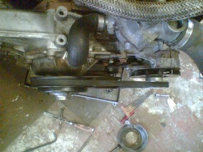
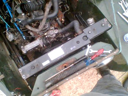
With the engine bolted to the gearbox, and the mounts secured
I was left with this: Tdi bolted up!
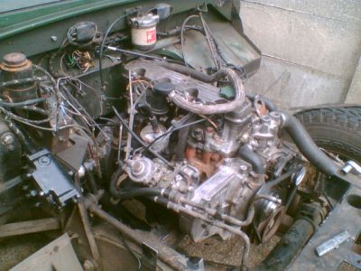
from
the otherside .
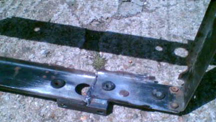
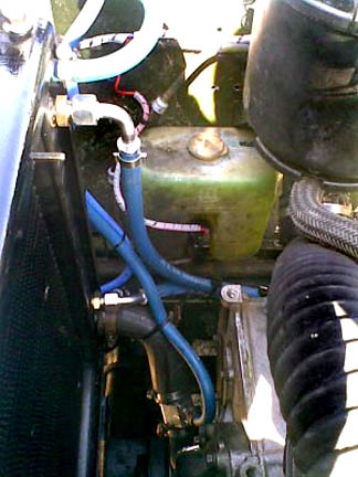
Just to confirm, once and for all, that an engine fitted with
a Discovery 200 Tdi timing cover will fit straight onto series
chassis mounts, here are some pictures:
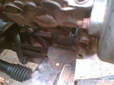
Right side.
Left side.
Right
side again, this time from underneath.
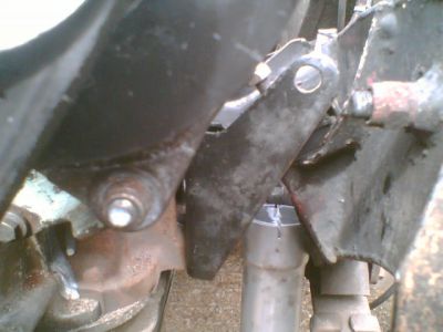
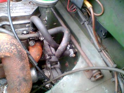
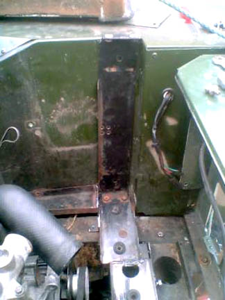
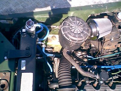
With the engine in I decided to experiment a little and answer
questions posed by others and myself about the Discovery manifold
set-up… Well, I can categorically say that:
Discovery
manifolds won’t fit in a 109” chassis without surgery.
As
you can see in the pictures the turbo body fouls the top rail of
the chassis by a good ½” to ¾”. I would
expect to have to take a scallop at least 1 ½” deep
to clear the turbo and allow for movement of the engine under load.
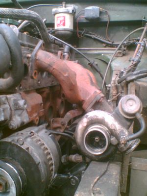
Discovery manifolds offered up.
I am aware that the manifold assembly will fit, just, in an 88”.
Rotating the turbo compressor housing (“clocking” it)
so that the outlet is at 10 or 11 o’clock, rather than 4
o’clock helps greatly. Using these manifolds does mean you
have to fabricate a tortuously routed exhaust header pipe though,
either down between the chassis rails and the starter motor, or
up and over the bulkhead mounting bracket and out through the wing
and down the front of the footwell 2.6 style.
Rotating the turbo 180 degrees on the manifold might give you
enough clearance against the chassis, although it would mean fabricating
new oil feed and return pipework, and the wategate actuator and
linkage would need modifying too. Putting the turbo outlet at the
front would simplify the exhaust routing though, by giving you
a little more room to operate.
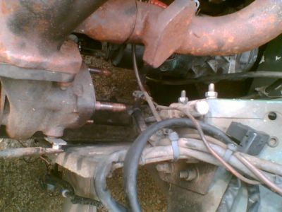
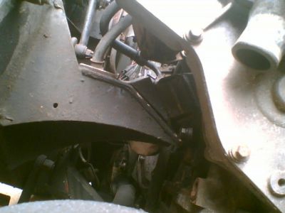
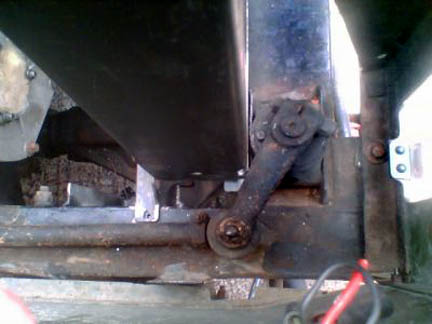
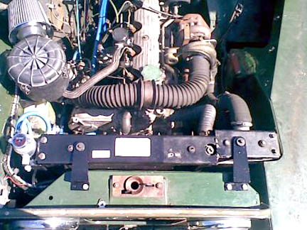
Dsicovery manifolds offered up
This
is the gap between you’d need to route the exhaust
through with a Discovery manifold – either down past the
starter and chassis, or up over the bulkhead bracket.
(NOTE FOR LHD: A LHD steering box takes up this
space meaning a power steering conversion would be mandentory - TJW)
For those people who have asked me about the fitting of a TDI
into a left-hand-drive vehicle, the above pictures demonstrate
that the Discovery manifolds are going to foul the steering gear
pretty terminally.
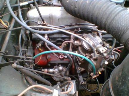
All is not lost, however as I am lucky to have been able to source
some Defender 200 TDI manifolds at reasonable cost via ebay (as
mentioned above). With the re-positioned alternator these bolt
straight on. A tip here is to fit and connect the starter motor
before you it the manifolds as things are very tight with them
on.
Left-hand-drive vehicle owners can also breathe a sigh of relief
as the Defender manifold assembly puts all the bits well out of
the way of LHD steering gear, as is evident in the next photo.
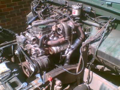
Defender manifolds fitted.
The exhaust header pipe you can see in the picture
above is part of a system supplied by Steve Parker Land Rovers
(01706 854222). In addition to their kits for installing alternative
engines into Series Land-Rovers they offer several alternative
tailor made exhaust systems, one of which is a Defender TDI into
a Series LWB with a rear fill tank. I decided to bite the bullet
and treat myself to one, as it will probably save me at least a
day of mucking about. It would be entirely possible to fabricate
a system using a 200TDI header, a Series 2.6 petrol tailpipe and
silencer and fabricating an intermediate pipe to suit, although
the cost saving would probably be offset by the time spent making
it!
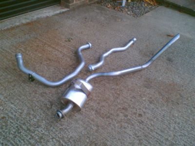
Steve Parker exhaust system for 200tdi & 109 station wagon.
Heater hoses connected
The heater pipes on the engine terminate, conveniently, right
next to the inlet pipes for the round Smiths heater that I have
fitted (mine is a 1959 Series II). The hose tail in the rear of
the cylinder head is the same thread (3/8” BSP) as the Series
item; in fact it’s identical to a Series III part. It’s
a larger bore than the corresponding Series II/IIA type so I swapped
them over as, after mucking about with the Discovery pipes for
a bit, I ended up using the pipes I had fitted with the old 2.25
engine. You could even fit a Series II/IIA style tap if you wanted
to, but I run mine open all the time.
The exhaust, I am pleased to report, went on perfectly. I will
say though, space is tight around its route and the larger bore
pipe requires much more careful positioning to prevent it hitting
anything. It took me the best part of a couple of hours to get
it right.
Next up is the fuel system. The previous owner of the engine had
helpfully removed everything with the aid of a Stanley knife, so
a quick trip to a mate to have a peer under the bonnet of his 90
was needed. The TDI system is quite straightforward – fuel
from the tank goes to the front port of the lift pump (the taller
of the two, usually marked “in”), then from the rear
port up to the fuel filter housing. From the fuel filter it goes
to the large single banjo fitting on the front top of the injector
pump (next to the timing cover). The injector spill pipe comes
from injector no. 1, back to a double banjo at the rear of the
injector pump (near the fuel cut-off solenoid), and from there
back to the tank. As I am using the original 2.25 filter housing
for the moment the top bleed-off port is now redundant and has
been blocked off.
I had planned on using a 2.25 lift pump to save having to change
the tank to pump pipe, but the actuating arms are a different shape
and the 2.25 one didn’t seem to engage on the camshaft properly
so I’ve stuck with the TDI one – probably for the best.
The battery is now re-sited under the passenger’s seat.
My underseat toolbox already had a well in it to accommodate a
battery (presumably because diesel II and IIA’s had twin
6volt batteries). Tray dimensions are: 310mm long x 185mm wide
x max 220mm high (including terminals). The battery I had fitted
in here OK, but if it hadn’t then I imagine buying a battery
of the right size would be easier than mucking about modifying
the tray. A length of 1” x 1” angle, two bits of M8
studding and some wingnuts make a serviceable battery clamp.
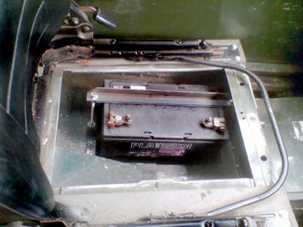
new battery home.
Wiring has been largely straightforward. As the starter solenoid
is in the same place as the 2.25 all the main cables fitted straight
to the terminal post without modification. Likewise the alternator
plugged straight in (admittedly only because I had already converted
to a Lucas alternator – if you still have a dynamo then you’ll
have to sort yourself out).
I have been advised that the TDI temperature sender won’t
work with the Series gauge, and have sourced an adapter from the
M16 x 1 thread in the head to take a standard Series sender. As
far as I am aware it is a standard 2.5 petrol item.
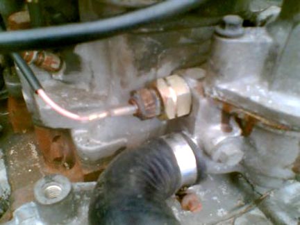
Temp sender. The adapter is a Land Rover part for a 2.5L petrol engine.
You need a switched live supply for the fuel cut-off solenoid
on the injector pump. Be aware, most Land-Rover diesel switches
cut the power to the electrical services when cranking, so you’ll
need to source a switch that keeps the current to at least one
switched live terminal when the engine cranks or you’ll never
get it to start! Luckily for me I had a switch identical to the
Series II type but with an additional switched live that does stay
on when cranking. This means I haven’t had to muck about
with an alternative (i.e. a petrol type) and I have been able to
retain the glow plugs “on the key” and not have to
worry about a separate switch or relay for them. Quite an elegant
solution, and one I am pleased with.
I have made up a short mini-loom for the engine comprising oil
pressure feed, water temperature feed and ignition switched live
to the injector pump. This is connected into the main loom at the
bulkhead. The only other wiring modifications were to remove the
Series glow plug ballast resistor and to connect the warning light
wires (that used to run in parallel across the resistor), one to
the glow plug terminal and the other to earth. I have also replaced
the 6volt 3watt glowplug warning lamp bulb with a 12volt 2.2watt
one.
My 2.25 engine used a Series III cable linkage as they are much
less prone to inducing unwelcome changes in engine speed caused
by movements of the engine/transmission assembly on it’s
mounts than the rod type. As I have several of them as spares,
and they are both short and cheap to replace I chose to use the
Series III cable (part number 598852) as the basis of my efforts.
I also wished to retain the hand throttle, so it was necessary
to come up with a solution that retained as much of the original
rod system as possible.
Connecting the actuating arm of the TDI pump is simply a matter
of using the 2.25’s pin and clip – it’s a perfect
fit. Next, the TDI pump has a bracket on its rear, terminating
in a 16mm hole for the original throttle cable. I bored a hole
through a M16 bolt, and slotted one side for the cable to pass
through (much like a bicycle brake cable adjuster). This secures,
with a thin nut and two washers, through the standard TDI bracket.
Next I took the original Series III throttle pull lever and cable
anchor and, using a small piece of 3mm plate, made a bracket that
would mount where the original cable anchor fitted to the bulkhead,
and hold the cable outer in a suitable place. Finally I used an
old piece of throttle link I had kicking about in the shed to pull
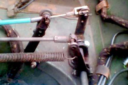
the inner. From the following pictures the eagle eyed amongst you
will no doubt notice I also moved the actuating arm inboard on
the top rod – this was purely for reasons of neatness. In
order to get full opening of the pump it was necessary to raise
the pedal height a few mm. If this feels awkward in use then I
have a slightly longer actuating arm to try.
Original series III cable operated throttle for 2.5L diesel.
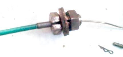
M16 bolt drilled and slotted to form cable mount.
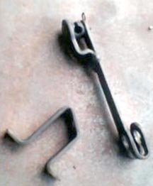
Original Series III cable pull and anchor.
|
Series III cable pull welded to a piece of 3mm plate, to
fit where original anchor did. Slight twist ensures smooth
cable run.
|
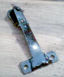
New cable anchor. Pull lever is standard part (number 277475).
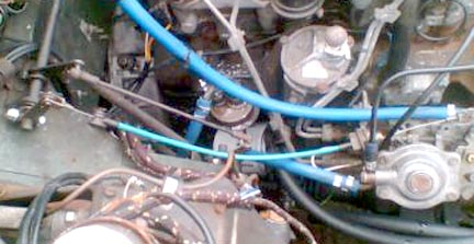
The completed linkage. Note, the link from the accelerator pedal
shaft has been moved inboard on the top cross shaft to allow a
smooth run for the cable.
200tdi into a Series land Rover - Alternative linkage for LHD
by TeriAnn
Glen's linkage will work just fine on LHD Series Land Rovers sold
in the US that came with a hand throttle. All you need to
do is order RHD SIII 2.5L throttle cable parts and follow Glen's
directions. However many Series Land Rovers were sold in
the US without a manual throttle. An alternative solution
requires sourcing a Defender 200tdi throttle pedal and a LHD Defender
200tdi throttle cable. The first step in this alternate method
is to remove the throttle pedal and all the old throttle linkage.
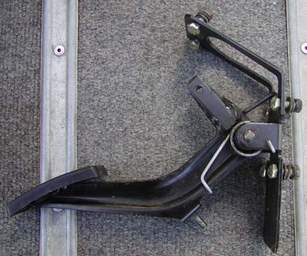 |
To the left is a throttle pedal from a Defender 200tdi. The
pedal bracket will not fit a Series Land Rover bulkhead without
minor modifications.
What you need to do is bend the base bisecting the lower
two mounting holes. You bend the bast towards the pedal.
In some case you may need to gind off some metal from the
undeerside of the pedal to achieve full open throttle.
|
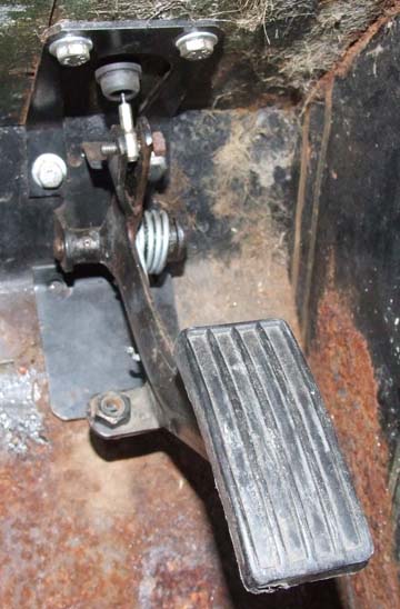
The picture to the right shows a modified Defender 200tdi
throttle pedal bolted in place.
Obviously you need to drill a hole forthe throttle cable
and add a bushing to keep the cable from being damaged You
may need to grind off part of the underside of the pedal where
it touches the base to achieve full throtle. |
 |
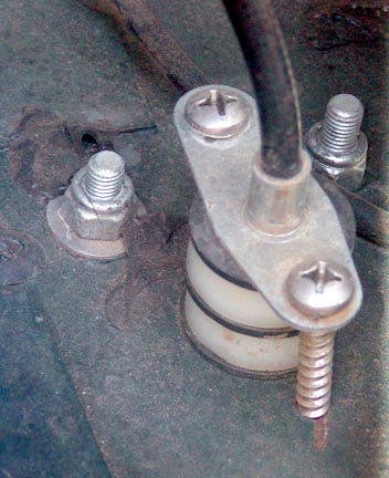 |
On the other side of the bulkhead I used a combination
of nylon and thin rubber spacers to take out any slackness
in the inner cable when the throttle pedal is in the up position. I
clamp that down with two sheet metal screws.
Thats all there is to it. |
With the engine connected in terms of fuel supply, electrical
connections and exhaust the next step to address was that of cooling.
Specifically the mounting of radiator and intercooler.
My main aim throughout the project has been to determine the best
possible combination of parts for the job, with reliability and
ease of future spares availability as major influences. That is
not to say that cost has been no object – I have tried to
keep costs to a minimum – but I have spent a great deal of
time considering the implications of spending money now as opposed
to both time and money in the future.
With the above in mind I have felt all along that it would be
necessary to use the Discovery radiator and intercooler, rather
than try and source any alternatives. The Discovery set-up has
the benefit of being guaranteed to do the job properly – as
well as being relatively inexpensive. Most of the conversions I
have viewed have placed the intercooler forward of the radiator,
above the chassis crossmember and hard up against the passenger
wing. This has required modification of the intercooler pipework,
meaning a future failure would require modification of a replacement – and
attendant delays whilst this is carried out. Further, mounting
the intercooler here causes problems by fouling with the Series
IIA’s inboard headlamps. I wanted to retain the standard
outward appearance of my vehicle and moving the headlamps out to
the wings was not part of the plan! The Discovery radiator has
an in-built water-to-oil cooler and is shallower but a little wider
and thicker than the original Series unit. In the Discovery it
is mounted on rubber bobbins within a frame that also contains
the intercooler. This mounting facilitates its removal and replacement
at cam-belt change time and I wanted to carry it over to my vehicle.
Some very careful measuring prior to removing the wings and front
panel revealed that, whilst things were fairly tight, there was
enough room to fit the standard Discovery parts in side by side
without modifying the wings or steering system. The steering relay
and drag-link limit the positioning of the radiator to the RHS,
and the shape of the inner wing on the LHS means the intercooler
has to be set back 22mm from the radiator. If you set back both
intercooler and radiator you run into clearance problems with the
waterpump.
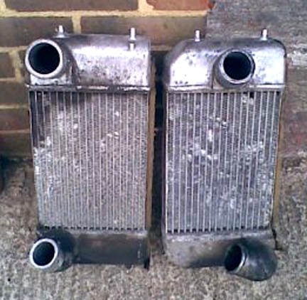
300tdi Defender / Discovery intercooler (left) and 200tdi intercooler
(right)
As you can see, both the 200 tdi and 300tdi intercoolers
have the same shape, and will fit in the same housing/framework,
but they have their inlets and outlets in different places. The
300TDI one would be good in the type of installation where it sat
infront of a standard series radiator as the ports are both on
the left hand side, pointing backwards.
If my information is correct a 200TDI Defender intercooler is
the same shape as these, but with both ports in the middle of the
top and bottom tanks, pointing backwards. If that is definitely
the case then that's the type that would fit neatest in my conversion
- although they would all fit and work.
The first task was to remove the original Series radiator
fixings from the radiator panel. The top edge was trimmed back
to just before the pressed step to allow the panel to retain
it’s
stiffness. The LHS was trimmed back further, largely removing
the angled fillet that would originally have ducted the incoming
air to the radiator but leaving a small fillet at the top to,
once again, lend stiffness to the top panel. The RHS was trimmed
back about an inch at the top and then chamfered back towards
the bottom.
View from LHS trimmed radiator panel
View from RHS
With this done the front wings were re-fitted. In the bottom of
the LHS wing is a pressed steel filler that bridges the gap between
the chassis top and the wing itself. As standard, this sits about
an inch or so above the top of the chassis rail. My intended intercooler
siting required removal or modification of this part as to sit
the intercooler above it would make things tight between the intercooler
and the bonnet. I cut and stepped it down so that it sat flush
with the chassis rail.
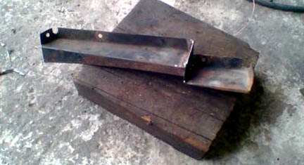
Modified filler panel
My chassis has two steering relay mounting holes, one each side
(not all do). This, conveniently, gave me ready-made mounting points
to anchor my radiator/intercooler frame to. Firstly I cut the frame
at the point where the intercooler and radiators meet. Then I bolted
two short sections of 25x25x3mm steel angle to the relay mounting
points. The frame section for the intercooler was positioned such
that it sat snug into the recess in the LHS wing and tacked into
place. The other (radiator) half was then offered up such that
it was as far forward as possible, giving maximum clearance from
the engine and also tacked into place. Once the positioning had
been checked and verified by dry-fitting the radiator and intercooler
the joins were seam welded and the top plate was similarly stepped
and welded to match. Two small feet were welded on the rear of
the frame, one each side, to support the rear against the top of
the chassis. These were drilled to take 6mm speed bolts that in
turn were screwed down into the top of the chassis.
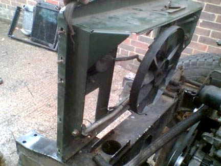
Steped radiator/intercoole mounting frame
Close-up of mounting detail
With the base of the frame bolted into position the
LHS upright was carefully trimmed to allow it to fit in the available
space. Basically the curved front return was removed, and a couple
of small notches cut into it to clear the inner wing. The mounting
for the Discovery radiator cowl was removed as it was both surplus
and in the way.
 |
Intercooler section of the mounting,
showing fitment adjacent to the modified filler panel
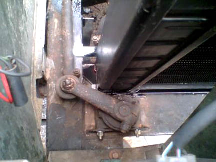
The RHS upright was trimmed slightly to clear the steering
relay top arm. The relay cleared the upright without modification,
but I chose to remove a small portion of it to be safe. The
radiator sits well inside the frame at this point and is
actually 12 to 15mm away from the arm even on full lock. |
Close-up showing clearance between steering link
and radiator mounting frame.
You can just see, in the pictures above, the two
small feet that support the rear of the frame against the chassis
top rail. I have made two top supports for the radiator using rubber
grommets picking up on the original top locating pins and securing
to the radiator panel either side of the bonnet lock.
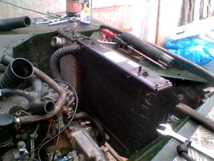
Radiator and intercooler in position
With the supporting framework modifications completed
I could fit a reconditioned radiator and begin plumbing in the
hoses. I had hoped to be able to use standard Discovery hoses,
but the radiator sits both higher and closer to the engine than
when in the donor vehicle and there was no way that they could
be persuaded to fit. Top hose pictured is a “universal” flexi-hose,
38mm diameter and 400mm long. It has an internal steel spiral,
which allows it to be bent in such a tight curve without collapsing.
This is a semi-permanent solution – I may replace it with
a silicon hose at some future point.
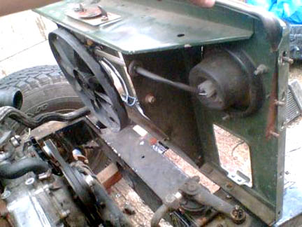
View from above
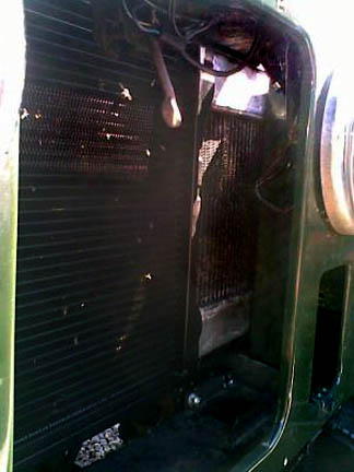 |
View from the front ahowing how the intercooler fits |
Steering gear clearance
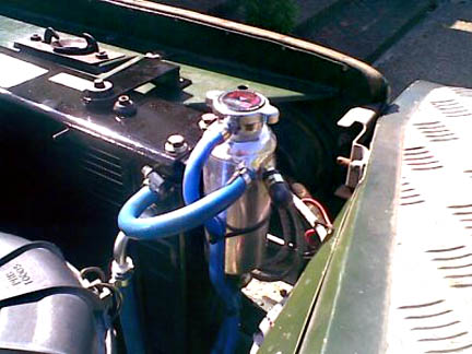
Header tank
The Discovery/Defender radiator doesn’t have
it’s own pressure cap and needs to be used in conjunction
with a pressurised header tank. The plastic Discovery tank I obtained
with the engine was too big and awkwardly shaped to be placed anywhere
sensible in the engine bay. The earlier 90/110 type I had, whilst
smaller physically, was also an awkward shape to find a home for
without having to also redesign the bonnet stay. As has been mentioned
before I wish to leave as much of the vehicle unmodified as possible – so
rather than have both a non-standard header tank and a non-standard
bonnet stay I chose to purchase a compact “universal” aluminium
header tank from a company called Car Builder Solutions (01580891309).
This is approximately 60mm diameter and 200mm long, and fits comfortably
down the side of the RHS radiator frame upright on a small bracket – leaving
plenty of clearance for the bonnet stay. It incorporates a small
size 1.1bar pressure cap, as found on most modern Japanese cars
and motorcycles.
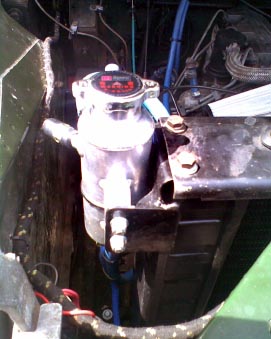
Header tank mounting
The bottom hose is currently made from two 90degree
bends cut from spare hoses, joined with a special adapter featuring
a hose tail. The hose tail is connected to the bottom of the header
tank. There is a vent hose at the top of the radiator; this is
connected to the top of the header tank to prevent air-locks. The
header tank has a further top inlet which is currently blocked
with a plug cap (supplied with the kit). In the future I may have
this inlet removed completely and welded up. Once my funds have
recovered a little I will replace the current bottom hose set-up
with more appropriately shaped silicon ones.
Next up was the connection of the oil cooler hoses. Initially
I managed to persuade the original discovery items to fit. The
problem with the Discovery hoses is that they are part flexi and
part rigid – in the Discovery they are clamped together and
held secure to the body with a bracket. With the radiator sat higher
and closer to the engine than before the pipes were simply the
wrong shapes to enable a sensible routing. I managed to ease them
into slow curves, which at least got them connected. I would not
like to say how long you could run with the pipes fitted unsupported
in this manner. I only did it to allow testing of the engine and
to enable me to drive the vehicle to a local hydraulic hose specialist
where I could organise the necessary fittings to make a neat and
safe connection.
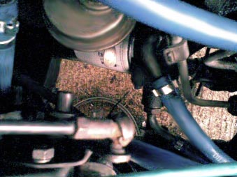
Original oil cooler pipes "persuaded" to
fit
It was necessary to retain the “short” adapters
from the oil filter end of the pipes, as they are non-standard “Land-Rover
specials”. The one from the top port of the filter housing
is a slightly less acute bend and, when fitted in the bottom port
instead, gives a nice smooth sweep towards the chassis rail. Fortunately
the other one is also better suited to being in the top port as
it then allows the top hose to sweep down to join it’s partner.
The new flexis now run along the inner edge of the chassis rail – the
bottom one secured with a “p” clip and the top one
cable-tied to it. At the radiator end, the original radiator-to-pipe
adapters were removed, as they couldn’t be matched to new
hose tails. Luckily the threads in the radiator are a standard
size (3/8” BSP), and hose tails are freely available to suit.
At the bottom I used a 45degree tail, and at the top a 90degree
one. I chose to use inexpensive “universal” 20Bar-air/oil/water
piping on grounds of cost. The pipes, adapters, fittings and clips
were less than £20. Ideally I would have preferred a set
of stainless-braided PTFE hoses, but at £80 plus I wanted
to make sure the routing was ok first – I may well change
them for braided ones before too long, maybe at the next oil change
if time and finances allow. Still, the results are pretty pleasing,
the new hoses loop neatly and smoothly down from the radiator,
along the chassis rail and to the oil filter housing.
The new oil cooler pipes have left plenty of room on the inner
wing for me to mount a Rover Montego Turbo Diesel air filter. This
is a neat round sealed plastic canister, piped inlet and outlets,
that came with it’s own mounting bracket from the donor car.
Filter cartridges are cheap at £2.12 each and, whilst I doubt
they’d be as good in the desert as genuine Land-Rover ones,
are designed for use with a similarly sized turbo diesel engine
so should be more than up to the job whilst driving around the
UK. I have mounted it as high up and as far forward as possible
without fouling the bonnet or the bonnet stay. It would be easy
to route the inlet to a snorkel should you so wish, but I have
fitted an additional cone filter for the time being. The outlet
is just about the same size as domestic drainpipe, and I used two
angled fittings to bring the port around to a convenient place
to attach the hose. The hose is a standard 2.25 diesel Series “elephant’s
trunk”, complete with its steady clip as removed from my
original engine. I used an inch of 50mm pipe as an adapter to step
the hose down to fit the turbo inlet, but other than that it fitted
without modification.
Oil filter end of new oil cooler pipes
 |
Radiator end of new oil cooler pipes |
Rover Montego Turbo Diesel air filter housing. The K&N
style cone filter is in addition to paper element inside the canister.
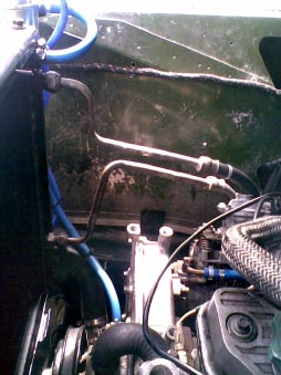
The breather hose from the rocker cover was shortened and swung
around to fit in the port at the bottom of the filter housing.
Routing of the breather hose
The Discovery 200TDI intercooler is currently plumbed
in with whatever scrap pieces of hose I had around from vehicles
previously broken. Whilst it fits, subsequent investigation has
shown that both 200TDI Defender and 300TDI Discovery/Defender
intercoolers have their inlet and outlet pipes in more user-friendly
locations. Once I have tracked down one I will swap them over
and tidy up the pipework. Turbo outlet pipe should go to the
bottom of the intercooler, and the top outlet from the intercooler
then goes to the inlet manifold.
I already had a Kenlowe fan fitted to the vehicle prior to the
engine swap. The relative positions of the waterpump and radiator
mean that a mechanical fan is now not an option so the electric
one has been re-fitted in front of the radiator. I have been
lead to believe the TDI engines normally run very cool, and seldom
need fan assistance for the cooling system. Currently a switch
in the cab triggers the fan, with a telltale lamp to indicate
it’s running. I may investigate fitting an automatic switch
in the top hose or the top of the radiator at some future point,
but it is not currently a priority.
Before the swap I had a Ford Transit washer bottle/pump assembly
fitted on the passenger side inner wing. The intercooler and
its associated piping now occupy that space so it was relocated
to the driver’s side.
Well, that’s pretty much it. In addition to the work detailed
above I have carried out an oil and filter change, fitted a new
fuel filter, changed the cam-belt and tensioners and set the
tappet clearances.
Further jobs to do include fitting a remote brake servo and
raising the final drive ratio by changing the differentials for
3.54:1 items. However these are outside the scope of this article.
Glen Anderson, July 2007.
Return to page top
|